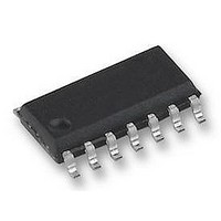
HEF4541BT NXP Semiconductors, HEF4541BT Datasheet - Page 4

HEF4541BT
Manufacturer Part Number
HEF4541BT
Description
IC, 4000 LOCMOS, SMD, 4541, SOIC14
Manufacturer
NXP Semiconductors
Type
Programmabler
Datasheet
1.HEF4541BT.pdf
(8 pages)
Specifications of HEF4541BT
Clock External Input
No
Supply Voltage Range
5V To 15V
Digital Ic Case Style
SOIC
No. Of Pins
14
Operating Temperature Range
-40°C To +70°C
Svhc
No SVHC (18-Jun-2010)
Frequency
100kHz
# Internal Timers
1
Quiescent Current
80uA
Propagation Delay Time
1150ns
Operating Supply Voltage (min)
3V
Operating Supply Voltage (typ)
3.3/5/9/12V
Operating Supply Voltage (max)
15V
Package Type
SO
High Level Output Current
-4.2mA
Low Level Output Current
4.2mA
Pin Count
14
Operating Temp Range
-40C to 85C
Operating Temperature Classification
Industrial
Mounting
Surface Mount
Base Number
4541
Rohs Compliant
Yes
Lead Free Status / RoHS Status
Lead free / RoHS Compliant
Available stocks
Company
Part Number
Manufacturer
Quantity
Price
Part Number:
HEF4541BT
Manufacturer:
NXP/恩智浦
Quantity:
20 000
Philips Semiconductors
PINNING
FREQUENCY SELECTION TABLE
RC oscillator
January 1995
A
MODE
AR
MR
PH
R
C
RS
0
TC
TC
Programmable timer
A
, A
Typical formula for oscillator
frequency:
H
H
L
L
0
Fig.4
1
f
osc
=
---------------------------------
2 3 R
A
External component connection for RC
oscillator; R
H
H
L
L
1
address inputs
mode select input
auto reset input
master reset input
phase input
external resistor connection (R
external capacitor connection (C
external resistor connection (R
external clock input
1
t
C
COUNTER STAGES n
t
NUMBER OF
S
2 R
13
10
16
8
t
.
t
S
)
) or
t
f
-------- -
f
)
osc
out
65 536
8 192
1 024
=
256
2
n
4
FUNCTION TABLE
Notes
1. For correct power-on reset, the supply voltage should
2. The timer is initialized on a reset pulse and the output
Timing component limitations
The oscillator frequency is mainly determined by
R
R
across the input protection diodes on the frequency. The
stray capacitance C2 should be kept as small as possible.
In consideration of accuracy, C
inherent stray capacitance. R
LOCMOS ‘ON’ resistance in series with it, which typically
is 500
V
The recommended values for these components to
maintain agreement with the typical oscillation formula are:
AR
DD
t
S
C
H
X
X
X
X
X
L
is to minimize the influence of the forward voltage
t
be above 8.5 V. For V
and connect AR to V
changes state after 2
state (latched). Reset of this latch is obtained by
master reset or by a LOW to HIGH transition on the
MODE input.
H = HIGH state (the more positive voltage)
L = LOW state (the less positive voltage)
X = state is immaterial
C
10 k
, provided R
= 15 V.
t
MR
H
L
L
L
L
L
L
100 pF, up to any typical value,
at V
INPUTS
R
DD
PH
t
X
X
X
X
X
H
L
= 5 V, 300
t
<< R
1 M .
MODE
S
X
X
X
H
X
X
L
and R
DD
n-1
DD
.
counts and remains in that
< 8.5 V, disable the autoreset
t
S
at V
MODE
auto reset disabled
auto reset enabled
master reset active
normal operation selected
division to output
single-cycle mode
output initially LOW,
after reset
output initially HIGH,
after reset
must be larger than the
C2 << R
t
must be larger than the
DD
= 10 V and 200
Product specification
HEF4541B
t
C
t
. The function of
(2)
(1)
MSI
at


