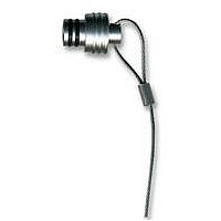
102.1947 FISCHER CONNECTORS, 102.1947 Datasheet - Page 6

102.1947
Manufacturer Part Number
102.1947
Description
SEALING CAP, MATING FACE OF RECEPTACLE
Manufacturer
FISCHER CONNECTORS
Datasheet
1.102.1947.pdf
(108 pages)
Specifications of 102.1947
Accessory Type
Sealing Cap
Rohs Compliant
Yes
For Use With
Mating Face Of The Receptacles
Lead Free Status / RoHS Status
Lead free / RoHS Compliant
A
Standardized Suffixes (Standard Code 1)
Clamp Set Distribution Guide for Cable Connectors
The following list describes the different types of clamp systems available:
Part number examples for Multipole and Triax:
Shielded:
Unshielded:
Sealed:
Part number examples for coax connectors ofall Series:
(For mixed contact connectors see page H8)
Insulator
Material
PEEK
PTFE
PBT
Series
1031
101
102
103
104
105
106
107
Plug
Type
Type
Type
Contact
Termin.
solder
solder
solder
crimp
crimp
S 104 A056-130
«S»
«U»
«E»
S, SA, SC, SV,
SOV, WS,
WSE, WSO,
K, DK, DKBE
KE, DKE
Multipole and Triax Connectors
S, K, DK - Clamp sets are included
Cable clamp:
Cable clamp:
Cable clamp:
S 102 A017 / 4.7
SE 102 A017 / 4.3
Chrome
Plating
natural
natural
natural
natural
natural
black
black
black
black
black
matt
for Shielded cable, when the shield is to be terminated to the connector body.
Shielded clamps can also be used for unshielded cable.
for Unshielded cable, or where the shield is not to be terminated to the connector body.
These clamps are available for series 102 through 105 and are slightly easier to assemble
as there is only one piece instead of three.
for Environmental applications, where the interface between cable and connector body must be
sealed. This type of clamp can be used for both shielded and unshielded cables.
Plug:
Plug:
Plug:
for cable of diameter 6.7mm
}
Guide
Mark
white
white
white
white
white
red
red
red
red
red
—
S 104 A056-130+
E3 104.3 / 6.7 + B
S 104 A056-130+
E3 104.6 / 6.7
S 104 A056-130+
E3 104.2 / 6.7 + B
Clamp sets should be ordered
separately, selected from
pages H1 - H7 and H9 - H10
For non-sealed coax connectors, the diameters are selected
from the tables for shielded clamps «S» and for sealed coax
connectors from the tables «E» on pages H1 - H7
STANDARDIZED SUFFIXES
ORDERING INFORMATION
Standard
-100
-110
-120
-130
-140
-150
-160
-60
-70
-80
-90
White Black Green Blue Yellow Red
-101
-111
-121
-131
-141
-151
-161
-61
-71
-81
-91
3
Strain Relief Color for Cable Connectors
-102
-112
-122
-132
-142
-152
-162
-62
-72
-82
-92
-103
-113
-123
-133
-143
-153
-163
-63
-73
-83
-93
Coax , Mixed and High Voltage Connectors
S, K, DK - Clamp sets are included
Clamp sets are included, but clamp diameter
should be added to the connector part number,
separated by a ‘/ ‘
Mixed coax and high voltage connectors are listed
on page H8.
-104
-114
-124
-134
-144
-154
-164
-64
-74
-84
-94
-115
-125
-165
-105
-135
-145
-155
-65
-75
-85
-95
-106
-116
-126
-136
-146
-156
-166
-66
-76
-86
-96
Grey
-107
-117
-127
-137
-147
-157
-167
-67
-77
-87
-97
solder contacts
DBP, DBPE,
DBPU with
-129
-139
-149
-69
-79
-89
-99
—
—
—
—


