E6C3-AG5B 360P/R 2M Omron, E6C3-AG5B 360P/R 2M Datasheet - Page 4
E6C3-AG5B 360P/R 2M
Manufacturer Part Number
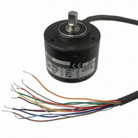
E6C3-AG5B 360P/R 2M
Description
ENCODER ROTARY 12-24V 360RES 2M
Manufacturer
Omron
Series
E6C3r
Datasheet
1.E69-DF5_5M.pdf
(9 pages)
Specifications of E6C3-AG5B 360P/R 2M
Encoder Type
Optical
Output Type
Gray Code (Absolute)
Pulses Per Revolution
360
Voltage - Supply
12 ~ 24VDC
Actuator Type
8mm Dia Flatted End
Detent
No
Built In Switch
No
Mounting Type
Chassis Mount
Orientation
Right Angle
Termination Style
Cable Leads
Lead Free Status / RoHS Status
Lead free / RoHS Compliant
Rotational Life (cycles Min)
-
Lead Free Status / Rohs Status
Lead free / RoHS Compliant
Other names
E6C3-AG5B360P/R2M
E6C3AG5B360PR2M
E6C3AG5B360PR2M


I/O Circuit Diagrams
Connection Specifications
Pre-wired Models
Note: Normally connect GND to 0 V or to an external ground.
Output
circuits
Output
mode
Wire color
Light blue
Model
Orange
Yellow
Brown
Purple
Green
White
Black
Gray
Blue
Pink
Red
---
Direction of rotation: CW (as viewed from end of shaft)
Resolution/12
Note: The circuit is the same for all
Model
E6C3-A
main circuit
Resolution of 8
A = 45˚, B = 22.5˚
C = 11.25˚
Resolution of 6
A = 60˚, B = 30˚
C = 15˚
Positioning
signal
bit outputs.
Strobe
signals
2
2
2
2
2
0
1
2
3
0
× 10
E6C3-AB5C
OFF
OFF
OFF
OFF
OFF
OFF
OFF
ON
ON
ON
ON
ON
ON
ON
No.
0
Shield
35 mA max.
30 VDC
E6C3-AN5C/-AN5B
1
6-bit (32 or 40)
Output signal
Not connected
Not connected
12 to 24 V
GND
Output
0 V
2
Positioning
Strobe
Parity
Absolute
Strobe
signal
3
2
2
2
2
2
2
angle
signal
0
1
2
3
4
5
4
Note: The circuit is the same for all
E6C3-A
main circuit
0˚
5
30˚
A
15˚
bit outputs.
B
6
30˚
E6C3-AB5B
12 to 24 VDC
7
7.5˚
C
1˚
8
60˚
35 mA
max.
Shield
0.5˚
9
Not connected
Not connected
Not connected
Not connected
Not connected
7.5˚
3-bit (6 or 8)
Positioning
10
90˚
12 to 24 V
GND
Strobe
Output
0 V
2
2
2
11
0.5˚
E6C3-AB5C/-AB5B
0
1
2
Shield (ground)
Output signal
0 V (common)
Direction of rotation: CW (as viewed from end of shaft) if rotation
direction input is high and CCW (as viewed from end of shaft) if
rotation direction input is low.
Note: The circuit is the same for all
Rotation Direction Input Circuit
E6C3-A
main circuit
Shaft angle:
360˚
2
2
2
2
2
2
2
2
T=360˚/256≈1.4˚
0
1
2
3
4
5
6
7
E6C3-A
main circuit
bit outputs.
Not connected
Not connected
Not connected
Positioning
(H)
E6C3-AN1E
(L)
5-bit (12)
2
Strobe
0
2
2
2
2
2.4
× 10
kΩ
0
1
2
3
1
Shield
°
35 mA
max.
2
T±T/2
3
5 VDC
Output
0 V
GND
4
5
T±T/2
Vcc (5 V or 12 V)
Input
0 V
6
Note: If the input is connected to Vcc, the
7
Rotation Direction Input
8
Note: The circuit is the same for all
output will increase for CW rotation
and if the input is connected to 0 V,
the output code will decrease for
CW rotation.
E6C3-AN1E/-AN2E
E6C3-A
main circuit
9
Output signal
Not connected
10
5 or 12 VDC
bit outputs.
8-bit (256)
11
E6C3-AN2E
12
2
2
2
2
2
2
2
2
13
0
1
2
3
4
5
6
7
8.2
kΩ
14
E6C3-A
15
Shield
35 mA
max.
16
17
12 VDC
Output
0 V
GND
18
19
4
Related parts for E6C3-AG5B 360P/R 2M
Image
Part Number
Description
Manufacturer
Datasheet
Request
R

Part Number:
Description:
ENCODER ROTARY 12-24V 1024RES 1M
Manufacturer:
Omron
Datasheet:
Part Number:
Description:
ENCODER ROTARY 12-24V 1024RES 2M
Manufacturer:
Omron
Datasheet:
Part Number:
Description:
ENCODER ROTARY 12-24V 256RES 1M
Manufacturer:
Omron
Datasheet:
Part Number:
Description:
ENCODER ROTARY 12-24V 256RES 2M
Manufacturer:
Omron
Datasheet:
Part Number:
Description:
ENCODER ROTARY 12-24V 360RES 1M
Manufacturer:
Omron
Datasheet:
Part Number:
Description:
ENCODER ROTARY 12-24V 720RES 1M
Manufacturer:
Omron
Datasheet:
Part Number:
Description:
ENCODER ROTARY 12-24V 720RES 2M
Manufacturer:
Omron
Datasheet:

Part Number:
Description:
G6S-2GLow Signal Relay
Manufacturer:
Omron Corporation
Datasheet:
Part Number:
Description:
Compact, Low-cost, SSR Switching 5 to 20 A
Manufacturer:
Omron Corporation
Datasheet:
Part Number:
Description:
Manufacturer:
Omron Corporation
Datasheet:
Part Number:
Description:
Manufacturer:
Omron Corporation
Datasheet: