LIS302ALB STMicroelectronics, LIS302ALB Datasheet - Page 9
LIS302ALB
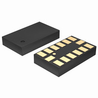
Manufacturer Part Number
LIS302ALB
Description
ACCELEROMETER 3AXIS MEMS 14-LGA
Manufacturer
STMicroelectronics
Datasheet
1.LIS302ALBTR.pdf
(17 pages)
Specifications of LIS302ALB
Axis
X, Y, Z
Acceleration Range
±2g
Sensitivity
0.145 x Vdd = V/g
Voltage - Supply
3 V ~ 3.6 V
Output Type
Analog
Bandwidth
2kHz
Interface
IC
Mounting Type
Surface Mount
Package / Case
14-LGA
Sensing Axis
X, Y, Z
Acceleration
2 g
Supply Voltage (max)
3.6 V
Supply Voltage (min)
3 V
Supply Current
0.65 mA
Maximum Operating Temperature
+ 85 C
Minimum Operating Temperature
- 40 C
Shutdown
Yes
For Use With
497-8204 - BOARD ADAPTER LIS302SG DIL24497-8203 - BOARD DEMO LIS302SG497-6246 - BOARD EVAL ACCELEROM LIS302ALK
Lead Free Status / RoHS Status
Lead free / RoHS Compliant
Available stocks
Company
Part Number
Manufacturer
Quantity
Price


LIS302ALB
3
3.1
3.2
3.3
Functionality
The LIS302ALB is an “piccolo” low-power, analog output three-axis linear accelerometer
packaged in a LGA package. The complete device includes a sensing element and an IC
interface able to take the information from the sensing element and to provide an analog
signal to the external world. The sensor provides the three accelerations and one
multiplexed analog output.
Sensing element
A proprietary process is used to create a surface micro-machined accelerometer. The
technology allows to carry out suspended silicon structures which are attached to the
substrate in a few points called anchors and are free to move in the direction of the sensed
acceleration. To be compatible with the traditional packaging techniques a cap is placed on
top of the sensing element to avoid blocking the moving parts during the moulding phase of
the plastic encapsulation.
When an acceleration is applied to the sensor the proof mass displaces from its nominal
position, causing an imbalance in the capacitive half-bridge. This imbalance is measured
using charge integration in response to a voltage pulse applied to the sense capacitor.
At steady state the nominal value of the capacitors are few pF and when an acceleration is
applied the maximum variation of the capacitive load is in fF range.
IC interface
The complete signal processing uses a fully differential structure, while the final stage
converts the differential signal into a single-ended one to be compatible with the external
world.
The first stage is a low-noise capacitive amplifier that implements a Correlated Double
Sampling (CDS) at its output to cancel the offset and the 1/f noise. The produced signal is
then sent to three different S&Hs, one for each channel, and made available to the outside.
The device provides an embedded multiplexer to allow the redirection of either the analog
output signals Voutx, Vouty, and Voutz or of an auxiliary input signal onto a single pin for
operation with a single channel A/D converter.
All the analog parameters (output offset voltage and sensitivity) are ratiometric to the
voltage supply. Increasing or decreasing the voltage supply, the sensitivity and the offset will
increase or decrease linearly. The feature provides the cancellation of the error related to
the voltage supply along an analog to digital conversion chain.
The product is factory calibrated at 3.3V. For availability of different supply voltage in the
maximum range [2.16V, 3.6V] contact factory
Factory calibration
The IC interface is factory calibrated for sensitivity (So) and Zero-g level (Voff).
The trimming values are stored inside the device in a non volatile structure. Any time the
device is turned on, the trimming parameters are downloaded into the registers to be
employed during the normal operation. This allows the user to employ the device without
further calibration.
Functionality
9/17
Related parts for LIS302ALB
Image
Part Number
Description
Manufacturer
Datasheet
Request
R

Part Number:
Description:
STMicroelectronics [RIPPLE-CARRY BINARY COUNTER/DIVIDERS]
Manufacturer:
STMicroelectronics
Datasheet:
Part Number:
Description:
STMicroelectronics [LIQUID-CRYSTAL DISPLAY DRIVERS]
Manufacturer:
STMicroelectronics
Datasheet:

Part Number:
Description:
BOARD EVAL FOR MEMS SENSORS
Manufacturer:
STMicroelectronics
Datasheet:
Part Number:
Description:
NPN TRANSISTOR POWER MODULE
Manufacturer:
STMicroelectronics
Datasheet:
Part Number:
Description:
TURBOSWITCH ULTRA-FAST HIGH VOLTAGE DIODE
Manufacturer:
STMicroelectronics
Datasheet:
Part Number:
Description:
Manufacturer:
STMicroelectronics
Datasheet:
Part Number:
Description:
DIODE / SCR MODULE
Manufacturer:
STMicroelectronics
Datasheet:
Part Number:
Description:
DIODE / SCR MODULE
Manufacturer:
STMicroelectronics
Datasheet:
Part Number:
Description:
Search -----> STE16N100
Manufacturer:
STMicroelectronics
Datasheet:
Part Number:
Description:
Search ---> STE53NA50
Manufacturer:
STMicroelectronics
Datasheet:
Part Number:
Description:
NPN Transistor Power Module
Manufacturer:
STMicroelectronics
Datasheet:
Part Number:
Description:
DIODE / SCR MODULE
Manufacturer:
STMicroelectronics
Datasheet: