SPMB250-A1 STMicroelectronics, SPMB250-A1 Datasheet
SPMB250-A1
Specifications of SPMB250-A1


Related parts for SPMB250-A1


SPMB250-A1 Summary of contents
Page 1
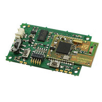
... Board dimensions ■ FCC compliant Description SPMB250-A1 board is a ready-to-use wireless acceleration sensor based on an IEEE 802.15.4 compliant radio designed to enable development of applications for remote motion monitoring in wireless sensor networks systems. The board is based on the ZigBee SPZB250 which performs both the RF radio and controlling functions and the three axis linear accelerometer sensor LIS3LV02DL ...
Page 2
... Power supply connector (J1 6 OFF switch (SW2 6.3 SIF connector (J2 6.4 Pad description . . . . . . . . . . . . . . . . . . . . . . . . . . . . . . . . . . . . . . . . . . . . . . 9 6.5 LED indicators . . . . . . . . . . . . . . . . . . . . . . . . . . . . . . . . . . . . . . . . . . . . . . 9 7 Board layout . . . . . . . . . . . . . . . . . . . . . . . . . . . . . . . . . . . . . . . . . . . . . . . 10 8 Soldering . . . . . . . . . . . . . . . . . . . . . . . . . . . . . . . . . . . . . . . . . . . . . . . . . 11 9 Recommendations . . . . . . . . . . . . . . . . . . . . . . . . . . . . . . . . . . . . . . . . . 12 10 Radiation pattern . . . . . . . . . . . . . . . . . . . . . . . . . . . . . . . . . . . . . . . . . . . 13 11 Mechanical dimensions . . . . . . . . . . . . . . . . . . . . . . . . . . . . . . . . . . . . . 14 12 Ordering information scheme . . . . . . . . . . . . . . . . . . . . . . . . . . . . . . . . 16 13 Revision history . . . . . . . . . . . . . . . . . . . . . . . . . . . . . . . . . . . . . . . . . . . 17 2/18 Doc ID 15179 Rev 2 SPMB250-A1 ...
Page 3
... SPMB250-A1 1 RoHS compliance ST modules are RoHS compliant and being based on ST devices comply with ECOPACK® norms implemented by ST. 2 Connections - pad out Figure 1. Connections Doc ID 15179 Rev 2 RoHS compliance 3/18 ...
Page 4
... Block diagram 3 Block diagram Figure 2. Block diagram 4/18 Doc ID 15179 Rev 2 SPMB250-A1 ...
Page 5
... SPMB250-A1 4 Maximum ratings 4.1 Absolute maximum ratings Table 1. Absolute maximum ratings Symbol V Board supply voltage CC T Operating ambient temperature OPmax T Storage temperature STG 4.2 Operating ranges Operating ranges define the limits for functional operation and parametric characteristics of the module. Functionality outside these limits is not implied Table 2 ...
Page 6
... Parameter Conditions Vin = 4 V Vin = 4 V Vin = 4 V Vin = 4 V @PER 2402 – 2480 MHz Full-scale = ±2 g Output data rate = 40 Hz Full-scale = ± bit representation Full-scale = ± bit representation Doc ID 15179 Rev 2 SPMB250-A1 Values Unit Min Typ Max 0.6 V 0.2 V 2.7 3 ...
Page 7
... SPMB250-A1 6 Board description 6.1 Power supply connector (J1) When used directly connected to the system to be monitored in terms of vibration / acceleration the only connection needed is the one related to the power source. To have a standard and in the same time miniaturized connection a two pole connector has been chosen (i.e. Molex 53261-0271 or equivalent) Figure 3 ...
Page 8
... To allow the user to program the board, a SIF connector is available. Signals available on this connector are: Figure 5. SIF - pin description Figure 6. SIF connector 8/18 Vdd 1 2 GND 3 4 GND 5 6 SIF_LOADB 7 8 PTI_EN 9 10 Doc ID 15179 Rev 2 SPMB250-A1 SIF_MISO SIF_MOSI SIF_CLK RSTB PTI_DATA ...
Page 9
... SPMB250-A1 6.4 Pad description When used on a motherboard the boundary pads on the SPMB250-A1 can be used to get the connections with the remaining part of the circuit present on the motherboard itself. The meaning of the pads is listed in the following table: Table 4. Pad description N. Pin name P1 J1 – ...
Page 10
... Board layout 7 Board layout Figure 7. Board layout 10/18 Doc ID 15179 Rev 2 SPMB250-A1 ...
Page 11
... SPMB250-A1 8 Soldering Soldering phase has to be carefully carried out: in order to avoid undesired melting phenomenon, particular attention has to be paid on the set up of the peak temperature. Here following some suggestions for the temperature profile based on IPC/JEDEC J-STD-020C, July 2004 recommendations. Table 5. Soldering ...
Page 12
... Avoid metallic parts close to the antenna – Do not use metallic case ● Board fixing can be done with 4 screws: – In case of fixing on metallic base insert an insulator foil between the board and the base in order to avoid any potential short circuit 12/18 Doc ID 15179 Rev 2 SPMB250-A1 ...
Page 13
... SPMB250-A1 10 Radiation pattern SPMB250-A1 is based on the SPZB250 module which incorporates an RF section with an integrated antenna (Murata ANCV12G44SAA127). The antenna radiation pattern (as measured on the SPZB250 module) follows. Figure 9. Measurement direction Doc ID 15179 Rev 2 Radiation pattern 13/18 ...
Page 14
... Mechanical dimensions 11 Mechanical dimensions In order to meet environmental requirements, ST offers these devices in different grades of ® ECOPACK packages, depending on their level of environmental compliance. ECOPACK specifications, grade definitions and product status are available at: www.st.com. ECOPACK trademark. Figure 10. Mechanical dimensions 14/18 Doc ID 15179 Rev 2 SPMB250-A1 ® ...
Page 15
... SPMB250-A1 Figure 11. Recommended land pattern Doc ID 15179 Rev 2 Mechanical dimensions 15/18 ...
Page 16
... Ordering information scheme 12 Ordering information scheme Table 6. Ordering information scheme Subsystem product MOTIONBEE™ family SN250 -based board Accelerometer sensor Version 1 16/18 MB 250 SP Doc ID 15179 Rev 2 SPMB250- ...
Page 17
... SPMB250-A1 13 Revision history Table 7. Document revision history Date 12-Feb-2009 03-Nov-2009 Revision 1 Initial release 2 Added Section 1 on page 3 Doc ID 15179 Rev 2 Revision history Changes 17/18 ...
Page 18
... Australia - Belgium - Brazil - Canada - China - Czech Republic - Finland - France - Germany - Hong Kong - India - Israel - Italy - Japan - Malaysia - Malta - Morocco - Philippines - Singapore - Spain - Sweden - Switzerland - United Kingdom - United States of America 18/18 Please Read Carefully: © 2009 STMicroelectronics - All rights reserved STMicroelectronics group of companies www.st.com Doc ID 15179 Rev 2 SPMB250-A1 ...