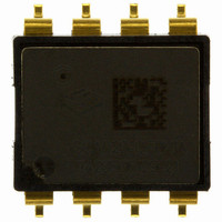
SCA620-CF8H1A VTI Technologies, SCA620-CF8H1A Datasheet

SCA620-CF8H1A
Specifications of SCA620-CF8H1A
Available stocks
Related parts for SCA620-CF8H1A
SCA620-CF8H1A Summary of contents
Page 1
Assembly Instructions for SCA6x0 and SCA10x0 series TABLE OF CONTENTS Table of Contents .....................................................................................................................1 1 Objective ..............................................................................................................................2 2 VTI'S DIL-8 and DIL-12 packages.......................................................................................2 3 Package Outline and Dimensions......................................................................................2 4 Tape and reel specifications ..............................................................................................3 5 Printed Circuit Board (PCB) Level ...
Page 2
... Figure 1: Three dimensional views of the DIL-8 and DIL-12 packages. 3 Package Outline and Dimensions The outline and dimensions for the DIL-8 package are presented in Figure 2. Figure 2: Outline and dimensions for DIL-8 package. VTI Technologies Oy www.vti.fi Assembly Instructions for SCA6x0 and SCA10x0 series TN71 2/12 ...
Page 3
... Packing tape dimensions are presented in figure 4. The unreeling direction and component polarity on tape are presented in figure 5. Reel dimensions are presented in figure 6. Figure 4: Packing tape dimensions for the DIL-8 and DIL-12 package. All dimensions in millimeters (mm). VTI Technologies Oy www.vti.fi Assembly Instructions for SCA6x0 and SCA10x0 series TN71 3/12 Rev ...
Page 4
... PIN 1 IDENTIFIER Figure 5: Package orientation on the tape and unreeling direction on tape 330 24 Figure 6: Reel dimensions. All dimensions in millimeters (mm). VTI Technologies Oy www.vti.fi Assembly Instructions for SCA6x0 and SCA10x0 series Direction of unreeling N min 2max 24.4 ± 2 102 30.4 DRAWING FOR REFERENCE ONLY M Ø13.0 ± 0.25 ...
Page 5
... VTI's MEMS components. Ultrasonic might destroy the MEMS structures. The solder paste which is used must be suitable for printing it through the stencil aperture dimensions. Type 3 paste is recommended (grain size 25-45µm). VTI Technologies Oy www.vti.fi Assembly Instructions for SCA6x0 and SCA10x0 series ...
Page 6
... If washing process is done after the soldering process, it must be noted that ultrasonic agitation wash after reflow is not allowed for VTI's DIL packaged MEMS components. As mentioned before (section 5.2) a no-clean paste is recommended. VTI Technologies Oy www.vti.fi Assembly Instructions for SCA6x0 and SCA10x0 series TN71 6/12 Rev ...
Page 7
... After bag is opened, devices that will be subjected to reflow solder or other high temperature process must be a) Stored at <10% RH Mounted within 168 hours of factor conditions ≤30 °C/60%RH. Note: Do not re-store devices that have exposed >10% RH conditions. VTI Technologies Oy www.vti.fi Assembly Instructions for SCA6x0 and SCA10x0 series TN71 7/12 Rev.1.0 ...
Page 8
... Cross- sectioning is a destructive inspection method. An example of a DIL solder joint cross-section in presented in Figure 9. Figure 9: Cross-section of the DIL package lead's solder joint (with eutectic SnPb solder). VTI Technologies Oy www.vti.fi Assembly Instructions for SCA6x0 and SCA10x0 series mag. ...
Page 9
... Place the component gently on top of the solder paste. To avoid solder bridging, push only very gently on top of the component. Melt the solder paste by putting the part through reflow oven or by using soldering iron as mentioned in the previous part. VTI Technologies Oy www.vti.fi Assembly Instructions for SCA6x0 and SCA10x0 series TN71 9/12 Rev ...
Page 10
... Same temperature is used both for Pb-free and SnPb-solder joints, even though SnPb solders melt already below 200ºC. Some temperature adjustment might be needed. Especially if tool head is old and 'dirty' temperature needs to be increased. VTI Technologies Oy www.vti.fi Assembly Instructions for SCA6x0 and SCA10x0 series ...
Page 11
... VTI does not recommend rework. 8 Environmental Aspects VTI Technologies respects environmental values and thus, its DIL packages are lead-free and RoHS compatible. VTI Technologies’ sensors should be soldered with lead-free solders in order to guarantee full RoHS compatibility. 9 References JEDEC / Electronic Industries Alliance, Inc ...
Page 12
... Document Change Control Version Date 1.0 22.04.2008 VTI Technologies reserves all rights to modify this document without prior notice. VTI Technologies Oy www.vti.fi Assembly Instructions for SCA6x0 and SCA10x0 series Change Description Release TN71 12/12 Rev.1.0 ...


