MNZB-EVB-900-B0 MeshNetics, MNZB-EVB-900-B0 Datasheet - Page 33
MNZB-EVB-900-B0
Manufacturer Part Number
MNZB-EVB-900-B0
Description
BOARD EVAL FOR MNZB-900-B0 W/ANT
Manufacturer
MeshNetics
Type
802.15.4/Zigbeer
Specifications of MNZB-EVB-900-B0
Frequency
868MHz, 915MHz
For Use With/related Products
MNZB-900-B0
Lead Free Status / RoHS Status
Lead free / RoHS Compliant
Other names
758-1008


© 2008 MeshNetics
4.3. Using the Boards
At node startup, current channel mask is regularly read from EEPROM. If channel mask
has been uploaded to EEPROM using Serial Bootloader, then no special action described
below is needed before starting WSNDemo. Nevertheless, if you need to upload channel
mask to EEPROM from flash (from an image file) then startup initialization of the node
must be performed as follows.
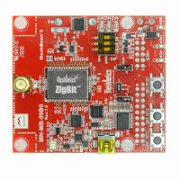
Press and hold the on-board SW1 button first (see Figure 2). Power ON the board with
holding the button pressed for at least 1 second. LED2 will get flashing 3 times. Next, all
LEDs will start flashing to indicate the node’s role: they will flash once on router, twice on
end device and three times on coordinator.
LED1, LED2 and LED3 will start blinking for 2 sec to indicate the acceptance of channel
mask in EEPROM.
NOTE:
When the operation described above is completed, the channel mask preloaded to
EEPROM is lost.
Starting the WSNDemo, do the following:
NOTE:
While WSNDemo is running, channel mask can be changed anytime by sending the
command through WSN Monitor (see Section 4.6.4). The channel mask which has been
issued from WSN Monitor and received by a node is permanently stored in the node’s
EEPROM, regardless of power-offs. To restore the default channel mask in EEPROM
repeat a node reinitializing procedure described above in this section or use Serial
Bootloader.
Table 13. DIP switch configurations used in WSNDemo
DIP-switches
1
ON
OFF
OFF
Coordinator organizes the wireless network automatically. Upon starting, any node
informs the network on its role. At that moment, LED1, LED2 and LED3 are flashing once
on router, they are flashing twice on end device and they are flashing three times on
coordinator.
After joining the network, a node starts sending data to the coordinator, which is indicated
by LEDs.
1.
2.
3.
4.
5.
Configure one single node as a coordinator, and make the others be routers and
end devices (see Table 13). Any of the boards provided can be configured with any
role.
Connect the coordinator node to the PC, using USB port on the coordinator board
Power on the coordinator node
Run WSN Monitor (see Section 4.6.1)
Power ON and reset the rest of the nodes.
2
OFF
ON
OFF
Z I G B I T ™ 9 0 0 D E V E L O P M E N T K I T 1 . 3
3
OFF
OFF
ON
Description
Board is configured to be a coordinator.
Board is configured to be a router.
Board is configured to be an end device.
U S E R ’ S G U I D E
Page 33/56
Related parts for MNZB-EVB-900-B0
Image
Part Number
Description
Manufacturer
Datasheet
Request
R

Part Number:
Description:
BOARD DEV 802.15.4/ZIGB PCB ANT
Manufacturer:
MeshNetics
Datasheet:

Part Number:
Description:
BOARD DEV 802.15.4/ZIGB CHIP ANT
Manufacturer:
MeshNetics
Datasheet:

Part Number:
Description:
BOARD DEV 802.15.4/ZIGB SMA CONN
Manufacturer:
MeshNetics
Datasheet:

Part Number:
Description:
BOARD EVAL MNZB-A24-UFL W/RP-SMA
Manufacturer:
MeshNetics

Part Number:
Description:
KIT DEV ZIGBIT 2.4GHZ COMPLETE
Manufacturer:
MeshNetics
Datasheet:
Part Number:
Description:
KIT DEV ZIGBIT 2.4GHZ LITE 45DAY
Manufacturer:
MeshNetics
Datasheet:


Part Number:
Description:
MOD 802.15.4/ZIGB 2.4GHZ RF PORT
Manufacturer:
MeshNetics
Datasheet:


Part Number:
Description:
KIT DEV ZIGBIT 900 COMPLETE 1YR
Manufacturer:
MeshNetics
Datasheet:

Part Number:
Description:
KIT DEV ZIGBIT 900 LITE 45DAYS
Manufacturer:
MeshNetics
Datasheet:


Part Number:
Description:
MOD 802.15.4/ZIGB 2.4GHZ CHIPANT
Manufacturer:
MeshNetics
Datasheet: