GCM188R71H103KA37D Murata, GCM188R71H103KA37D Datasheet - Page 18
GCM188R71H103KA37D
Manufacturer Part Number
GCM188R71H103KA37D
Description
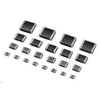
Multilayer Ceramic Capacitors (MLCC) - SMD/SMT 0603 0.01uF 50volts X7R 10%
Manufacturer
Murata
Series
GCMr
Datasheets
1.GCM188R71C105KA64D.pdf
(50 pages)
2.GCM188R71H103KA37D.pdf
(1 pages)
3.GCM155R71C104KA55D.pdf
(2 pages)
Specifications of GCM188R71H103KA37D
Voltage Rating
50 Volts
Operating Temperature Range
- 55 C to + 125 C
Temperature Coefficient / Code
X7R
Product
Automotive MLCCs
Dimensions
0.8 mm W x 1.6 mm L x 0.8 mm H
Termination Style
SMD/SMT
Capacitance
0.01 uF
Tolerance
10 %
Package / Case
0603 (1608 metric)
Lead Free Status / RoHS Status
Lead free / RoHS Compliant
Available stocks
Company
Part Number
Manufacturer
Quantity
Price
Company:

Part Number:
GCM188R71H103KA37D
Manufacturer:
MURATA
Quantity:
640 000
Company:
Part Number:
GCM188R71H103KA37D
Manufacturer:
MURATA
Quantity:
32 000
Part Number:
GCM188R71H103KA37D 0603 X7R 103K 50V
Manufacturer:
MURATA/村田
Quantity:
20 000


1
!Note
• This PDF catalog is downloaded from the website of Murata Manufacturing co., ltd. Therefore, it’s specifications are subject to change or our products in it may be discontinued without advance notice. Please check with our
• This PDF catalog has only typical specifications because there is no space for detailed specifications. Therefore, please approve our product specifications or transact the approval sheet for product specifications before ordering.
sales representatives or product engineers before ordering.
!Note
16
No.
18
19
20
Specifications and Test Methods
Continued from the preceding page.
Board
Flex
Terminal
Strength
Beam Load Test
• Please read rating and !CAUTION (for storage, operating, rating, soldering, mounting and handling) in this catalog to prevent smoking and/or burning, etc.
• This catalog has only typical specifications because there is no space for detailed specifications. Therefore, please approve our product specifications or transact the approval sheet for product specifications before ordering.
AEC-Q200
Test Item
Appearance
Capacitance
Change
Q/D.F.
I.R.
Appearance
Capacitance
Change
Q/D.F.
I.R.
Temperature Compensating Type
No marking defects
Within ±5.0% or ±0.5pF
(Whichever is larger)
30pF min.: QU1000
30pF max.: QU400+20C
C: Nominal Capacitance (pF)
More than 10,000MΩ or 500Ω · F
(Whichever is smaller)
No marking defects
Within the specified tolerance
30pF min.: QU1000
30pF max.: QU400+20C
C: Nominal Capacitance (pF)
More than 10,000MΩ or 500Ω · F
(Whichever is smaller)
The chip endure following force.
< Chip L dimension: 2.5mm max. >
< Chip L dimension: 3.2mm min. >
Chip thickness G 0.5mm rank: 20N
Chip thickness V 0.5mm rank: 8N
Chip thickness F 1.25mm rank: 15N
Chip thickness U 1.25mm rank: 54.5N
Specifications
*1
Within ±10.0%
W.V.: 25Vmin.: 0.025 max.
W.V.: 16V: 0.035 max.
W.V.: 25Vmin.: 0.025 max.
W.V.: 16V: 0.035 max.
*1
High Dielectric Type
GCM Series Specification and Test Methods
100
Fig. 1
C
a
b
t: 1.6mm
(GCM03/15: 0.8mm)
*1
*1
Solder the capacitor on the test jig (glass epoxy board) shown in
Fig. 1 using a eutectic solder. Then apply a force in the direction
shown in Fig. 2 for 5±1sec. The soldering should be done by the
reflow method and should be conducted with care so that the
soldering is uniform and free of defects such as heat shock.
Solder the capacitor to the test jig (glass epoxy board) shown in
Fig. 3 using a eutectic solder. Then apply *18N force in parallel
with the test jig for 60sec.
The soldering should be done either with an iron or using the
reflow method and should be conducted with care so that the
soldering is uniform and free of defects such as heat shock.
*2N (GCM03/15)
Place the capacitor in the beam load fixture as Fig. 4.
Apply a force.
< Chip Length: 2.5mm max. >
Speed supplied the Stress Load: 0.5mm / sec.
< Chip Length: 3.2mm min. >
Speed supplied the Stress Load: 2.5mm / sec.
GCM03
GCM15
GCM18
GCM21
GCM31
GCM32
GCM03
GCM15
GCM18
GCM21
GCM31
GCM32
Type
Type
Capacitance meter
R4
45
AEC-Q200 Test Method
Fig. 3
20
Fig. 4
0.3
0.5
0.6
0.8
2.0
2.0
0.3
0.4
1.0
1.2
2.2
2.2
L
a
a
114
0.6
Fig. 2
45
Continued on the following page.
Pressunzing
speed: 1.0mm/sec
Pressurize
Iron Board
Flexure: V2
(High Dielectric Type)
Flexure: V3
(Temperature
Compensating Type)
0.9
1.5
2.2
3.0
4.4
4.4
0.9
1.5
3.0
4.0
5.0
5.0
Solder resist
Baked electrode or
copper foil
b
b
c
(t=1.6mm
GCM03/15: 0.8mm)
1.65
0.3
0.6
0.9
1.3
1.7
2.6
0.3
0.5
1.2
2.0
2.9
c
c
(in mm)
(in mm)
C03E.pdf
09.3.31
Related parts for GCM188R71H103KA37D
Image
Part Number
Description
Manufacturer
Datasheet
Request
R

Part Number:
Description:
Murata Microblower 20x20 DCDC Driver Board - Samples Only
Manufacturer:
Murata
Part Number:
Description:
357-036-542-201 CARDEDGE 36POS DL .156 BLK LOPRO
Manufacturer:
Murata
Datasheet:
Part Number:
Description:
Manufacturer:
Murata
Datasheet:
Part Number:
Description:
Manufacturer:
Murata
Datasheet:
Part Number:
Description:
Manufacturer:
Murata
Datasheet:
Part Number:
Description:
Manufacturer:
Murata
Datasheet:
Part Number:
Description:
Manufacturer:
Murata
Datasheet:
Part Number:
Description:
Manufacturer:
Murata
Datasheet:
Part Number:
Description:
Manufacturer:
Murata
Datasheet:
Part Number:
Description:
BLM21BD751SN1On-Board Type (DC) EMI Suppression Filters
Manufacturer:
Murata
Datasheet:
Part Number:
Description:
BLM15AG100SN1On-Board Type (DC) EMI Suppression Filters
Manufacturer:
Murata
Datasheet:
Part Number:
Description:
NFE31PT222Z1E9On-Board Type (DC) EMI Suppression Filters
Manufacturer:
Murata
Datasheet:
Part Number:
Description:
Chip Coil
Manufacturer:
Murata
Datasheet:
Part Number:
Description:
Chip Coil
Manufacturer:
Murata
Datasheet: