DK-DEV-5M570ZN Altera, DK-DEV-5M570ZN Datasheet - Page 19
DK-DEV-5M570ZN
Manufacturer Part Number
DK-DEV-5M570ZN
Description
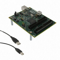
KIT DEV MAX V 5M570Z
Manufacturer
Altera
Series
MAX® Vr
Type
CPLDr
Datasheets
1.DK-DEV-5M570ZN.pdf
(30 pages)
2.DK-DEV-5M570ZN.pdf
(2 pages)
3.DK-DEV-5M570ZN.pdf
(30 pages)
4.DK-DEV-5M570ZN.pdf
(164 pages)
5.DK-DEV-5M570ZN.pdf
(24 pages)
Specifications of DK-DEV-5M570ZN
Contents
Board, Cable(s), Software and Documentation
Silicon Manufacturer
Altera
Core Architecture
CPLD
Core Sub-architecture
MAX
Silicon Core Number
5M
Silicon Family Name
MAX V
Kit Contents
MAX V CPLD Development Board, USB Cable
Rohs Compliant
Yes
Lead Free Status / RoHS Status
Lead free / RoHS Compliant
For Use With/related Products
5M570ZF256
Lead Free Status / Rohs Status
Compliant
Other names
544-2722
Available stocks
Company
Part Number
Manufacturer
Quantity
Price


Chapter 2: Board Components
General User Input/Output
General User Input/Output
Table 2–15. User-Defined Push-Button Switch Schematic Signal Names and Functions
Table 2–16. User-Defined Push-Button Switch Component Reference and Manufacturing Information
Table 2–17. User-Defined LED Schematic Signal Names and Functions
January 2011 Altera Corporation
Board Reference
Board Reference
Board Reference
S1, S2
D8
D7
S2
S1
User-Defined Push-Button Switches
User-Defined LEDs
User-defined LEDs.
Driving a logic 0 on the I/O port
illuminates the LED. Driving a logic 1
on the I/O port turns off the LED.
User-defined push-button switch.
When the switch is pressed and held
down, the device pin is set to logic 0;
when the switch is released, the
device pin is set to logic 1.
Push-button switches
This section describes the user I/O interface to the CPLD, including the push-buttons
and status LEDs.
The development board includes two user-defined push-button switches. Board
references S1 (USER_PB1) and S2 (USER_PB0) are push-button switches that allow you to
interact with the MAX V CPLD device. There is no board-specific function for these
user-defined push-button switches.
Table 2–15
corresponding MAX V CPLD device pin numbers.
Table 2–16
manufacturing information.
The development board includes two general purpose LEDs. Board references D7
(USER_LED1) and D8 (USER_LED0) are user-defined LEDs which allow status and
debugging signals to be driven to the LEDs from the CPLD designs loaded into the
MAX V CPLD device. There is no board-specific function for these LEDs.
Table 2–17
MAX V CPLD pin numbers.
Description
Description
Description
lists the user-defined push-button switch schematic signal names and their
lists the user-defined LED schematic signal names and their corresponding
lists the user-defined push-button switch component reference and the
Dawning Precision Co., Ltd. TS-A02SA-2-S100
Manufacturer
Schematic Signal
Signal Name
USER_LED0
USER_LED1
Schematic
USER_PB0
USER_PB1
Name
Manufacturer
Part Number
MAX V CPLD Development Board Reference Manual
I/O Standard
I/O Standard
3.3-V
3.3-V
www.dawning2.com.tw
Manufacturer Website
MAX V CPLD Device
MAX V CPLD Device
Pin Number
Pin Number
R1
P4
M9
R3
2–13
Related parts for DK-DEV-5M570ZN
Image
Part Number
Description
Manufacturer
Datasheet
Request
R

Part Number:
Description:
KIT DEV ARRIA II GX FPGA 2AGX125
Manufacturer:
Altera
Datasheet:

Part Number:
Description:
KIT DEV CYCLONE III LS EP3CLS200
Manufacturer:
Altera
Datasheet:

Part Number:
Description:
KIT DEV STRATIX IV FPGA 4SE530
Manufacturer:
Altera
Datasheet:

Part Number:
Description:
KIT DEV FPGA 2AGX260 W/6.375G TX
Manufacturer:
Altera
Datasheet:

Part Number:
Description:
KIT DEV STRATIX V FPGA 5SGXEA7
Manufacturer:
Altera
Datasheet:

Part Number:
Description:
KIT DEVELOPMENT STRATIX III
Manufacturer:
Altera
Datasheet:

Part Number:
Description:
KIT DEVELOPMENT STRATIX IV
Manufacturer:
Altera
Datasheet:

Part Number:
Description:
KIT DEV ARRIA GX 1AGX60N
Manufacturer:
Altera
Datasheet:
Part Number:
Description:
KIT STARTER CYCLONE IV GX
Manufacturer:
Altera
Datasheet:
Part Number:
Description:
KIT DEVELOPMENT STRATIX IV
Manufacturer:
Altera
Datasheet:

Part Number:
Description:
CPLD, EP610 Family, ECMOS Process, 300 Gates, 16 Macro Cells, 16 Reg., 16 User I/Os, 5V Supply, 35 Speed Grade, 24DIP
Manufacturer:
Altera Corporation
Datasheet:
Part Number:
Description:
CPLD, EP610 Family, ECMOS Process, 300 Gates, 16 Macro Cells, 16 Reg., 16 User I/Os, 5V Supply, 15 Speed Grade, 24DIP
Manufacturer:
Altera Corporation
Datasheet: