DK-DEV-5M570ZN Altera, DK-DEV-5M570ZN Datasheet - Page 11
DK-DEV-5M570ZN
Manufacturer Part Number
DK-DEV-5M570ZN
Description
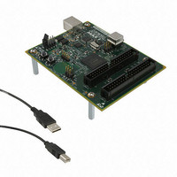
KIT DEV MAX V 5M570Z
Manufacturer
Altera
Series
MAX® Vr
Type
CPLDr
Datasheets
1.DK-DEV-5M570ZN.pdf
(30 pages)
2.DK-DEV-5M570ZN.pdf
(2 pages)
3.DK-DEV-5M570ZN.pdf
(30 pages)
4.DK-DEV-5M570ZN.pdf
(164 pages)
5.DK-DEV-5M570ZN.pdf
(24 pages)
Specifications of DK-DEV-5M570ZN
Contents
Board, Cable(s), Software and Documentation
Silicon Manufacturer
Altera
Core Architecture
CPLD
Core Sub-architecture
MAX
Silicon Core Number
5M
Silicon Family Name
MAX V
Kit Contents
MAX V CPLD Development Board, USB Cable
Rohs Compliant
Yes
Lead Free Status / RoHS Status
Lead free / RoHS Compliant
For Use With/related Products
5M570ZF256
Lead Free Status / Rohs Status
Compliant
Other names
544-2722
Available stocks
Company
Part Number
Manufacturer
Quantity
Price


Chapter 2: Board Components
Configuration, Status, and Setup Elements
Table 2–4. MAX V CPLD Device I/O Pin Count and Usage (Part 2 of 2)
Configuration, Status, and Setup Elements
January 2011 Altera Corporation
Push-Buttons
User LEDs
I
SPI EEPROM
Clock
Device I/O Total:
2
C EEPROM
Configuration
Function
This section describes the board's configuration, status, and setup elements.
The MAX V CPLD development board supports the following device configuration
methods:
■
■
CPLD Configuration over Embedded USB-Blaster
The USB-Blaster is implemented using a USB Type-B connector (J4), a FTDI USB 2.0
PHY device (U3), and an Altera MAX II CPLD EPM240M100 (U4). This allows the
configuration of the MAX V CPLD using a USB cable which connects between the
USB port on the board (J4) and a USB port of a PC running the Quartus II software.
The JTAG chain is normally mastered by the embedded USB-Blaster found in the
MAX II CPLD EPM240M100.
Embedded USB-Blaster is the default method for configuring the CPLD at any
time using the Quartus II Programmer in JTAG mode with the supplied USB cable.
External USB-Blaster for configuring the CPLD using a JTAG connector. To use this
optional method to configure the CPLD, you have to mount the JTAG connector or
header to the back of the board.
I/O Standard
3.3-V CMOS
I/O Count
109/159
2
2
2
4
1
Push-button 2: Dev_CLRn
MAX V CPLD Development Board Reference Manual
Special Pins
—
—
—
—
2–5
Related parts for DK-DEV-5M570ZN
Image
Part Number
Description
Manufacturer
Datasheet
Request
R

Part Number:
Description:
KIT DEV ARRIA II GX FPGA 2AGX125
Manufacturer:
Altera
Datasheet:

Part Number:
Description:
KIT DEV CYCLONE III LS EP3CLS200
Manufacturer:
Altera
Datasheet:

Part Number:
Description:
KIT DEV STRATIX IV FPGA 4SE530
Manufacturer:
Altera
Datasheet:

Part Number:
Description:
KIT DEV FPGA 2AGX260 W/6.375G TX
Manufacturer:
Altera
Datasheet:

Part Number:
Description:
KIT DEV STRATIX V FPGA 5SGXEA7
Manufacturer:
Altera
Datasheet:

Part Number:
Description:
KIT DEVELOPMENT STRATIX III
Manufacturer:
Altera
Datasheet:

Part Number:
Description:
KIT DEVELOPMENT STRATIX IV
Manufacturer:
Altera
Datasheet:

Part Number:
Description:
KIT DEV ARRIA GX 1AGX60N
Manufacturer:
Altera
Datasheet:
Part Number:
Description:
KIT STARTER CYCLONE IV GX
Manufacturer:
Altera
Datasheet:
Part Number:
Description:
KIT DEVELOPMENT STRATIX IV
Manufacturer:
Altera
Datasheet:

Part Number:
Description:
CPLD, EP610 Family, ECMOS Process, 300 Gates, 16 Macro Cells, 16 Reg., 16 User I/Os, 5V Supply, 35 Speed Grade, 24DIP
Manufacturer:
Altera Corporation
Datasheet:
Part Number:
Description:
CPLD, EP610 Family, ECMOS Process, 300 Gates, 16 Macro Cells, 16 Reg., 16 User I/Os, 5V Supply, 15 Speed Grade, 24DIP
Manufacturer:
Altera Corporation
Datasheet: