EVL90WADP-LLCSR STMicroelectronics, EVL90WADP-LLCSR Datasheet - Page 5
EVL90WADP-LLCSR
Manufacturer Part Number
EVL90WADP-LLCSR
Description
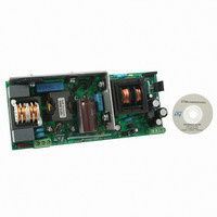
EVAL BOARD PORTABLE PWR SUPPLY
Manufacturer
STMicroelectronics
Type
Power Factor Correctionr
Datasheets
1.L6563HTR.pdf
(49 pages)
2.L6599ADTR.pdf
(36 pages)
3.EVL90WADP-LLCSR.pdf
(29 pages)
4.EVL90WADP-LLCSR.pdf
(28 pages)
Specifications of EVL90WADP-LLCSR
Main Purpose
AC/DC, Primary and Secondary Side with PFC
Outputs And Type
1, Isolated
Power - Output
90W
Voltage - Output
19V
Current - Output
4.75A
Voltage - Input
90 ~ 264VAC
Regulator Topology
Boost
Frequency - Switching
130kHz
Board Type
Fully Populated
Utilized Ic / Part
L6563H, L6599A, SRK2000
Input Voltage
90 V to 264 V
Output Voltage
19 V
Dimensions
65 mm x 155 mm
Product
Power Management Modules
Supply Current
4.75 A
Lead Free Status / RoHS Status
Lead free / RoHS Compliant
For Use With/related Products
L6563H, L6599A, SRK2000
Other names
497-10377


AN3014
1
Main characteristics and circuit description
The main features of the SMPS are:
●
●
●
●
●
●
●
●
●
The circuit is composed of two stages: a front-end PFC using the L6563H, and a LLC
resonant converter based on the L6599A. The SRK2000 controls the synchronous
rectification on the secondary side. The PFC stage works as a preregulator and powers the
resonant stage with a constant voltage of 400 V. The downstream converter operates only if
the PFC is on and regulating. In this way, the resonant stage can be optimized for a narrow
input voltage range.
Startup sequence
As indicated previously, the PFC acts as master and the resonant stage can operate only if
the PFC output is delivering the nominal output voltage. Therefore the circuit is designed so
that at startup the PFC starts first, then the downstream converter turns on. Initially, the
L6563H is supplied by the integrated high voltage startup circuit, but as soon as the PFC
starts switching, a charge pump connected to the PFC inductor supplies both the PFC and
resonant controllers. Once both stages have been activated, the controllers are supplied
also by the auxiliary winding of the resonant transformer, assuring correct supply voltage
even during standby operation.
Because the L6563H integrated HV startup circuit is turned off and therefore is not
dissipative during normal operation, it significantly contributes to the reduction of power
consumption when the power supply operates at light load, in accordance with current
world-wide standby consumption standards.
Brownout protection
Brownout protection prevents the circuit from working with abnormal mains levels. It is easily
achieved using the RUN pin (pin12) of the L6563H. This pin is connected through a resistor
divider to the VFF pin (pin 5), which provides the mains voltage peak value information. An
internal comparator enables the IC operations if the mains level is correct, within the
nominal limits. At startup, if the input voltage is below 90 Vac (typ), circuit operations are
inhibited.
The L6599A has similar protection on the LINE pin (pin 7). It is used to prevent the resonant
converter from working with too low an input voltage, which can cause incorrect capacitive
mode operation. If the bulk voltage (PFC output) is below 380 V, the resonant startup is not
allowed. The L6599A internal comparator has a hysteresis which allows the turn-on and
turn-off voltage to be set independently. The turn-off threshold has been set to 300 V in
Universal input mains range: 90 − 264 Vac, frequency 45 − 65 Hz
Output voltage: 19 V at 4.75 A continuous operation
Mains harmonics: according to EN61000-3-2 class-D or JEITA-MITI class-D
Standby mains consumption: < 0.26 W at 230 Vac
Efficiency at nominal load: > 92% at 115 Vac
EMI: according to EN55022-class-B
Safety: according to EN60950
Dimensions: 65 x 155 mm, 25 mm maximum component height
PCB: double-sided, 70 µm, FR-4, mixed PTH/SMT
Doc ID 16064 Rev 1
Main characteristics and circuit description
5/28
Related parts for EVL90WADP-LLCSR
Image
Part Number
Description
Manufacturer
Datasheet
Request
R

Part Number:
Description:
STMicroelectronics [RIPPLE-CARRY BINARY COUNTER/DIVIDERS]
Manufacturer:
STMicroelectronics
Datasheet:
Part Number:
Description:
STMicroelectronics [LIQUID-CRYSTAL DISPLAY DRIVERS]
Manufacturer:
STMicroelectronics
Datasheet:

Part Number:
Description:
BOARD EVAL FOR MEMS SENSORS
Manufacturer:
STMicroelectronics
Datasheet:
Part Number:
Description:
NPN TRANSISTOR POWER MODULE
Manufacturer:
STMicroelectronics
Datasheet:
Part Number:
Description:
TURBOSWITCH ULTRA-FAST HIGH VOLTAGE DIODE
Manufacturer:
STMicroelectronics
Datasheet:
Part Number:
Description:
Manufacturer:
STMicroelectronics
Datasheet:
Part Number:
Description:
DIODE / SCR MODULE
Manufacturer:
STMicroelectronics
Datasheet:
Part Number:
Description:
DIODE / SCR MODULE
Manufacturer:
STMicroelectronics
Datasheet:
Part Number:
Description:
Search -----> STE16N100
Manufacturer:
STMicroelectronics
Datasheet:
Part Number:
Description:
Search ---> STE53NA50
Manufacturer:
STMicroelectronics
Datasheet:
Part Number:
Description:
NPN Transistor Power Module
Manufacturer:
STMicroelectronics
Datasheet:
Part Number:
Description:
DIODE / SCR MODULE
Manufacturer:
STMicroelectronics
Datasheet: