142-1701-561 Emerson Network Power, 142-1701-561 Datasheet - Page 251
142-1701-561
Manufacturer Part Number
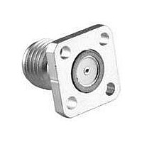
142-1701-561
Description
CONN JACK .015" GOLD SMA
Manufacturer
Emerson Network Power
Series
SMAr
Datasheet
1.133-3711-801.pdf
(294 pages)
Specifications of 142-1701-561
Connector Style
SMA
Connector Type
Jack, Female Sockets
Contact Termination
Solder
Impedance
50 Ohm
Mounting Type
Panel Mount, Square Flange
Fastening Type
Threaded
Frequency - Max
26.5GHz
Frequency-max
26.5GHz
Product
Connector
Lead Free Status / RoHS Status
Lead free / RoHS Compliant
Features
-
Color
-
Cable Group
-
Lead Free Status / Rohs Status
Lead free / RoHS Compliant
Other names
1421701561
J556
J556


BNC Twist-on Plugs and Jacks Field Installable
CABLE ASSEMBLY CAUTIONS:
•
•
•
CPFI-UG88-10
CPFI-UG78-2
CPFI-UG78-5
CPFI-UG88-1
CPFI-UG88-2
CPFI-UG88-3
CPFI-UG88-4
CPFI-UG88-5
CPFI-UG89-2
Series are designed for solid center conductor wire. RG-58 cable will need the
center conductor tin dipped (ONLY if it is not a solid center conductor). This is
necessary to provide extra support for step 5.
RG-MATV-59 cable will require caution when using the fingernail to rotate the
braids on cable types that include aluminum foil for the outer conductor. DO
NOT tear or rip the foil conductor to the 1/32" as suggested by step 3.
RG-62 cable includes trimming the filament to 9/16" as well. Make sure that
the filament does not unravel so that it protrudes past this dimension.
PART
NO.
Connectivity Solutions
RG-TFE-59, 62
BELDEN 8281
RG-MATV-59
RG-59, 62
RG-59, 62
RG-59, 62
CABLE
RG-58
TYPE
RG-6
RG-6
Tel: 800-247-8256
GAUGE
WIRE
22
18
20
22
20
20
18
22
22
.025 (0.64)
.040 (1.02)
.032 (0.81)
.025 (0.64)
.032 (0.81)
.032 (0.81)
.040 (1.02)
.025 (0.64)
.025 (0.64)
DECIMAL
WIRE
•
Fax: 507-833-6287
.220 (5.59)-.250 (6.35)
.270 (6.86)-.280 (6.35)
.185 (4.07)-.205 (5.21)
.220 (5.59)-.250 (6.35)
.272 (6.91)-.307 (7.80)
.220 (5.59)-.250 (6.35)
.270 (6.86)-.280 (7.11)
.185 (4.07)-.205 (5.21)
.220 (5.59)-.250 (6.35)
JACKET
Assembly Instructions
O.D.
•
www.EmersonNetworkPower.com/connectivity
INCHES (MILLIMETERS) • CUSTOMER DRAWINGS AVAILABLE ON REQUEST
1. Identify connector parts. (1 piece)
2. Trim cable as shown. Taking care not
3. Use the fingernail to rotate the outer
4. Gently insert the center conductor
5. Firmly push the cable home (a slight
to nick the center conductor or outer
braid.
braids clockwise such that 1/32" of the
insulation is bared. Then in the same
direction rub the stray braids flat. (Stray
or loose braids can cause shorts.)
down the back end of the connector,
feeding it into the guide hole. (If the
center conductor is not in place,
approximately 1/8" of the center
conductor—the part closest to the
dielectric —will still be viewable.)
clockwise twist may help with inser-
tion). Then screw the connector on the
cable in a clockwise direction until it is
snugly attached to the jacket.
251
Related parts for 142-1701-561
Image
Part Number
Description
Manufacturer
Datasheet
Request
R

Part Number:
Description:
CONN JACK FLANGE MOUNT GOLD
Manufacturer:
Emerson Network Power
Datasheet:


Part Number:
Description:
CONN JACK RECEPT 4HOLE FLNG MNT
Manufacturer:
Emerson Network Power

Part Number:
Description:
CONN JACK .015 PIN .016 CIR.
Manufacturer:
Emerson Network Power
Datasheet:

Part Number:
Description:
CONN JACK .018" NICKEL SMA
Manufacturer:
Emerson Network Power

Part Number:
Description:
RF Connectors PC END BLKHD JCK GLD .074" BOARDS
Manufacturer:
Emerson Network Power

Part Number:
Description:
AC/DC Front end 12Vo 36A 12Vsb Standard Airflow
Manufacturer:
Emerson Network Power

Part Number:
Description:
POWER SUPPLY DIN 24VDC 10A
Manufacturer:
Emerson Network Power
Datasheet:

Part Number:
Description:
POWER SUPPLY SGL 48VOUT 40W 3X5"
Manufacturer:
Emerson Network Power
Datasheet:

Part Number:
Description:
POWER SUP MED&ITE 48V 45W 2"X4"
Manufacturer:
Emerson Network Power
Datasheet:

Part Number:
Description:
POWER SUPPLY 60W 12V OUT
Manufacturer:
Emerson Network Power
Datasheet:

Part Number:
Description:
POWER SUPPLY 60W 48V OUT
Manufacturer:
Emerson Network Power
Datasheet:

Part Number:
Description:
POWER SUPPLY 60W 15V OUT
Manufacturer:
Emerson Network Power
Datasheet:

Part Number:
Description:
POWER SUPPLY TRPL 3.3/5/12V 40W
Manufacturer:
Emerson Network Power
Datasheet:

Part Number:
Description:
POWER SUPPLY SWITCHER 24V 40W
Manufacturer:
Emerson Network Power
Datasheet: