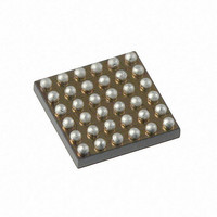
AS1119-BWLT austriamicrosystems, AS1119-BWLT Datasheet - Page 25

AS1119-BWLT
Manufacturer Part Number
AS1119-BWLT
Description
IC LED 144CH DRIVER 36WLCSP
Manufacturer
austriamicrosystems
Datasheet
1.AS1119-BWLT.pdf
(31 pages)
Specifications of AS1119-BWLT
Display Type
LED
Configuration
Dot Matrix
Interface
I²C
Current - Supply
4mA
Voltage - Supply
2.7 V ~ 5.5 V
Operating Temperature
-40°C ~ 85°C
Mounting Type
Surface Mount
Package / Case
36-UFBGA, 36-WLCSP
Lead Free Status / RoHS Status
Lead free / RoHS Compliant
Digits Or Characters
-
Other names
AS1119-BWLTTR
Available stocks
Company
Part Number
Manufacturer
Quantity
Price
Company:
Part Number:
AS1119-BWLT
Manufacturer:
MITSUBISHI
Quantity:
76
Part Number:
AS1119-BWLT
Manufacturer:
AMS
Quantity:
20 000
AS1119
Datasheet - R e g i s t e r D e s c r i p t i o n
Table 19. Display Option Register Format
AS1119 Config Register (0x04)
In this register the configuration of the charge pumps is set to 2 or 3 blocks. The direction of the SYNC_xxx pin (input
or output) is also set. Per default this register is set to 0x00.
Table 20. AS1119 Config Register Format
Current Source Block A, B, C Registers (0x05, 0x06, 0x07)
Within this registers the current for one block of LEDs can be set from 0mA to 31mA in 255 steps (8 bits). Per default
this register is set to 0x00.
Table 21. Current Sourcer Register Format
www.austriamicrosystems.com/LED-Driver-ICs/AS1119
Bit
3:0
Bit
7:3
2:1
Bit
7:0
7:0
0
number of displayed
Matrix Configuration
current sources in
Analog Current
Analog Current
(scan-limit)
one frame
Bit Name
Bit Name
Bit Name
Matrix A
Matrix B
Sync
-
Address 0x05
Address 0x06
Default
Default
Default
0000000
0000000
00000
0111
00
0
0x03 Display Option Register
0x04 AS1119 Config Register
Access
Access
Access
Current Source Registers
R/W
R/W
R/W
R/W
R/W
n/a
00: do not use
0000: CS0
0001: CS0 to CS1
0010: CS0 to CS2
0011: CS0 to CS3
0100: CS0 to CS4
0101: CS0 to CS5
0110: CS0 to CS6
0111: CS0 to CS7
1000: CS0 to CS8
0000: CS0
0001: CS0 to CS1
0010: CS0 to CS2
0011: CS0 to CS3
0100: CS0 to CS4
0101: CS0 to CS5
01: pin B6 is used as clk output for synchronization
10: pin B6 is used as clk input for synchronization
11: do not use
0: 3 matrixes (à 5x6 LED-Matrix)
1: 2 matrixes (à 8x9 LED-Matrix)
00000000: 0mA
..........
11111111: 31mA
00000000: 0mA
..........
11111111: 31mA
Revision 1.03
Matrix A
Matrix A
2 Matrix setting
0000: CS0
0001: CS0 to CS1
0010: CS0 to CS2
0011: CS0 to CS3
0100: CS0 to CS4
0101: CS0 to CS5
0110: CS0 to CS6
0111: CS0 to CS7
1000: CS0 to CS8
0000: CS6
0001: CS6 to CS7
0010: CS6 to CS8
0011: CS6 to CS9
0100: CS6 to CS10
0101: CS6 to CS11
3 Matrixes setting
Bit Description
Bit Description
Bit Description
Matrix B
Matrix B
0000: CS12
0001: CS12 to CS13
0010: CS12 to CS14
0011: CS12 to CS15
0100: CS12 to CS16
0101: CS12 to CS17
Matrix C
25 - 31


