PIC16F721-I/ML Microchip Technology, PIC16F721-I/ML Datasheet - Page 3
PIC16F721-I/ML
Manufacturer Part Number
PIC16F721-I/ML
Description
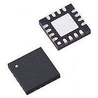
MCU PIC 4K FLASH 20-QFN
Manufacturer
Microchip Technology
Series
PIC® XLP™ 16Fr
Datasheets
1.PIC16F722-ISS.pdf
(8 pages)
2.PIC16LF720-ISS.pdf
(244 pages)
3.PIC16F720-ISO.pdf
(36 pages)
4.PIC16F720-ISO.pdf
(8 pages)
5.PIC16F721-IML.pdf
(6 pages)
Specifications of PIC16F721-I/ML
Core Size
8-Bit
Program Memory Size
7KB (4K x 14)
Peripherals
Brown-out Detect/Reset, POR, PWM, WDT
Core Processor
PIC
Speed
16MHz
Connectivity
I²C, SPI, UART/USART
Number Of I /o
17
Program Memory Type
FLASH
Ram Size
256 x 8
Voltage - Supply (vcc/vdd)
1.8 V ~ 5.5 V
Data Converters
A/D 12x8b
Oscillator Type
Internal
Operating Temperature
-40°C ~ 85°C
Package / Case
20-VFQFN Exposed Pad
Controller Family/series
PIC16F
No. Of I/o's
18
Ram Memory Size
256Byte
Cpu Speed
16MHz
No. Of Timers
3
Lead Free Status / RoHS Status
Lead free / RoHS Compliant
Eeprom Size
-
Lead Free Status / RoHS Status
Lead free / RoHS Compliant


Silicon Errata Issues
1. Module: AUSART
1.1 OERR Flag Not Clearing
1.2 Starting the Interrupt Service Routine
2011 Microchip Technology Inc.
Note:
The OERR flag of the RCSTA register is reset only
by either clearing the CREN bit of the RCSTA
register or by a device Reset. Clearing the SPEN
bit of the RCSTA register does not clear the OERR
flag.
Work around
Clear the OERR flag by clearing the CREN bit in
lieu of clearing the SPEN bit.
Affected Silicon Revisions
When the AUSART is configured for Synchronous
mode and either an RCIF or TXIF flag event wakes
the device from Sleep, then execution of the
Interrupt
immediately after the two instructions following the
SLEEP instruction have finished executing.
Work around
Follow the SLEEP instruction with two NOP
instructions or two instructions desired to be
executed before the ISR begins.
Affected Silicon Revisions
A3
A3
X
X
This document summarizes all silicon
errata issues from all revisions of silicon,
previous as well as current. Only the
issues indicated by the shaded column in
the following tables apply to the current
silicon revision (as applicable).
Service
Routine
(ISR)
will
begin
2. Module: Interrupts
The
addresses to the stack when vectoring to the
interrupt vector. Specifically, the interrupt vector
address 0x4 is incorrectly pushed to the stack after
the current PC, at the time the interrupt was
received, is pushed. This will cause the stack to
overflow if the user program is operating seven
calls deep when an interrupt arrives. Because the
stack is circular, the overflow causes the first stack
address to be overwritten.
Work around
Disable interrupts by clearing the GIE bit in the
INTCON register whenever the user program is
operating seven calls deep. This ensures that
interrupts will not cause the stack to overflow.
Affected Silicon Revisions
A3
X
PIC16(L)F720/721
interrupt
logic incorrectly pushes two
DS80521A-page 3
Related parts for PIC16F721-I/ML
Image
Part Number
Description
Manufacturer
Datasheet
Request
R

Part Number:
Description:
MCU PIC 4K FLASH 20-SOIC
Manufacturer:
Microchip Technology
Datasheet:

Part Number:
Description:
MCU PIC 4K FLASH 20-SSOP
Manufacturer:
Microchip Technology
Datasheet:

Part Number:
Description:
MCU PIC 4K FLASH 20-DIP
Manufacturer:
Microchip Technology
Datasheet:

Part Number:
Description:
7 KB FLASH, 256 B SRAM, 18 I/O 20 QFN 4x4mm TUBE
Manufacturer:
Microchip Technology
Datasheet:
Part Number:
Description:
7 KB FLASH, 256 B SRAM, 18 I/O 20 PDIP .300in TUBE
Manufacturer:
Microchip Technology
Datasheet:
Part Number:
Description:
7 KB FLASH, 256 B SRAM, 18 I/O 20 SOIC .300in TUBE
Manufacturer:
Microchip Technology
Datasheet:
Part Number:
Description:
7 KB FLASH, 256 B SRAM, 18 I/O 20 SSOP .209in TUBE
Manufacturer:
Microchip Technology
Datasheet:

Part Number:
Description:
IC PIC MCU FLASH 2KX14 28-QFN
Manufacturer:
Microchip Technology
Datasheet:

Part Number:
Description:
IC PIC MCU FLASH 2KX14 28-SOIC
Manufacturer:
Microchip Technology
Datasheet:

Part Number:
Description:
IC PIC MCU FLASH 2KX14 28DIP
Manufacturer:
Microchip Technology
Datasheet:
Part Number:
Description:
IC PIC MCU FLASH 2KX14 28-SOIC
Manufacturer:
Microchip Technology
Datasheet:
Part Number:
Description:
IC PIC MCU FLASH 2KX14 28QFN
Manufacturer:
Microchip Technology

Part Number:
Description:
IC PIC MCU FLASH 2KX14 28SSOP
Manufacturer:
Microchip Technology
Part Number:
Description:
IC PIC MCU FLASH 2KX14 8-SSOP
Manufacturer:
Microchip Technology
Datasheet:
Part Number:
Description:
IC PIC MCU FLASH 2KX14 28-SSOP
Manufacturer:
Microchip Technology
Datasheet: