H3DE-M2AC/DC24-230 Omron, H3DE-M2AC/DC24-230 Datasheet - Page 4
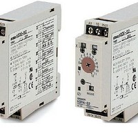
H3DE-M2AC/DC24-230
Manufacturer Part Number
H3DE-M2AC/DC24-230
Description
Stopwatches / Timers MULTI-FUN SOLID STAT
Manufacturer
Omron
Type
Multifunctionr
Specifications of H3DE-M2AC/DC24-230
Timing Range
0.1 s to 120 Hrs
Supply Voltage
25 VAC to 230 VAC, 24 VDC to 28 VDC
Accuracy
+/- 1 %
Current Rating (max)
5 A
Display Type
Hand Dial
Operating Temperature Range
- 10 C to + 55 C
Termination Style
Screw
Time Range
0.1 Sec. To 120 Hr.
Supply Voltage Max
230VDC
Time Range Max
120h
Switch Function
DPDT
Time Range Min
0.1s
Supply Voltage Min
24VDC
Lead Free Status / RoHS Status
Lead free / RoHS Compliant
Lead Free Status / RoHS Status
Lead free / RoHS Compliant, Lead free / RoHS Compliant


■ Characteristics
Note: 1. With the H3DE-M@, if the voltage exceeds 26.4 VAC/DC, the following hold at signal OFF for C, D, and G modes:
Accuracy of operating
time
Setting error
Signal input time
Influence of voltage
Influence of temperature ±2% max. of FS (±2%±10 ms max. at 1.2-s range)
Insulation resistance
Dielectric strength
Vibration resistance
Shock resistance
Contact material
Impulse withstand volt-
age
Noise immunity
Static immunity
Life expectancy
EMC
Degree of protection
Weight
2. For reference: A maximum current of 0.15 A can be switched at 125 VDC (cosφ=1).
Accuracy of operating time: ±1% ±50 ms max. at 1.2-s range
Setting error: ±10% +100/-50 ms max.
Signal input time: 100 ms min.
A maximum current of 0.1 A can be switched if L/R is 7 ms.
In both cases, a life of 100,000 operations can be expected.
The minimum applicable load is 10 mA at 5 VDC (failure level: P).
±1% max. of FS (±1% ±10 ms max. at 1.2-s range) (see note 1)
±10% ±50 ms max. of FS (see note 1)
50 ms min. (see note 1)
±0.5% max. of FS (±0.5% ±10 ms max. at 1.2-s range)
100 MΩ min. at 500 VDC
Between current-carrying metal parts and exposed non-current-carrying metal parts: 2,000 VAC for 1 min.
Between control output terminals and operating circuit: 2,000 VAC for 1 min.
Between contacts of different polarities: 2,000 VAC for 1 min.
Between contacts not located next to each other: 1,000 VAC for 1 min.
Malfunction: 0.5-mm single amplitude at 10 to 55 Hz
Destruction: 0.75-mm single amplitude at 10 to 55 Hz
Malfunction: 100 m/s
Destruction: 1,000 m/s
AGNi+gold plating (Use the G6RN-1 at 12 VDC.)
3 kV (between power terminals)
4.5 kV (between current-carrying metal parts and exposed non-current-carrying metal parts)
Square-wave noise generated by noise simulator (pulse width: 100 ns/1 µs, 1-ns rise) ±1.5 kV
Malfunction: 4 kV
Destruction: 8 kV
Mechanical: 10 million operations min. (under no load at 1,800 operations/h)
Electrical:
(EMI)
Emission Enclosure:
Emission AC Mains:
Harmonic Current:
Voltage Fluctuation and Flickering:
(EMS)
Immunity ESD:
Immunity RF-interference from AM Radio Waves: EN61000-4-3: 10 V/m (80 MHz to 1 GHz) (level 3)
Immunity Burst:
Immunity Surge:
IP30 (Terminal block: IP20)
120 g
100,000 operations min. (5 A at 250 VAC, resistive load at 360 operations/h)
(see note 2)
2
2
EN61812-1
EN55011 Group 1 class B
EN55011 Group 1 class B
EN61000-3-2
EN61000-3-3
EN61812-1
EN61000-4-2: 6 kV contact discharge (level 3)
EN61000-4-4: 2 kV power port and output port (level 3)
EN61000-4-5: 2 kV common mode (level 3)
8 kV air discharge (level 3)
1 kV control port with capacitive clamp (level 3)
1 kV differential mode (level 3)
H3DE-M/-S
4