H5CX-AD-N AC24/DC12-24 Omron, H5CX-AD-N AC24/DC12-24 Datasheet - Page 5
H5CX-AD-N AC24/DC12-24
Manufacturer Part Number
H5CX-AD-N AC24/DC12-24
Description
Stopwatches / Timers SCREW TERM RLY OUT Multi-Function
Manufacturer
Omron
Series
H5CXr
Datasheet
1.Y92P-CXT4B.pdf
(44 pages)
Specifications of H5CX-AD-N AC24/DC12-24
Timing Range
0.001 s to 9999 Hrs
Supply Voltage
12 V to 24 V
Current Rating (max)
100 mA
Display Type
4 Digit LCD Backlight
Product
Digital Timer
Termination Style
Screw
Time Range
0.001s-9999hrs
Power Consumption
2.4W
Reset Time
20ms
Character Size
11.5mm
Mounting Type
Panel
Time Range Min
0.001s
Supply Voltage Min
12V
Connector Type
Screw Terminal
Relay Type
Integrated
Function
Programmable (Multi-Function)
Circuit
SPDT (1 Form C)
Delay Time
0.001 Sec ~ 9999 Hrs
Output Type
Mechanical Relay
Contact Rating @ Voltage
5A @ 250VAC
Voltage - Supply
12 ~ 24VDC, 24VAC
Timing Adjustment Method
DIP Switches
Timing Initiate Method
Input Voltage, Trigger Signal
No. Of Digits / Alpha
4
Rohs Compliant
Yes
Lead Free Status / RoHS Status
Lead free / RoHS Compliant
For Use With
PNP/NPN
Lead Free Status / RoHS Status
Lead free / RoHS Compliant, Lead free / RoHS Compliant


* Not supported by the H5CX-A11@ or H5CX-L8@.
Specifications
Ratings
*1. Do not use the output from an inverter as the power supply. The ripple must be 20% maximum for DC power.
*2. Inrush current will flow for a short time when the power supply is turned ON.
*3. The display is lit only when the power is ON. Nothing is displayed when power is OFF.
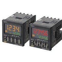
• Switch the display color* between red, green, and orange
• Up/Down Keys for each digit enable easy operation.
• Cyclic control is easy with the Twin Timer and Variable
Item
Classification
Ratings
Mounting method
External connections
Degree of protection
Digits
Time ranges
Timer mode
Inputs
Reset system
Power reset
Reset voltage
Sensor waiting time
Output
Display method
Memory backup
Operating temperature range
Storage temperature range
Operating humidity range
Case color
Attachments
to see the output status from a distance.
ON/OFF Duty modes.
Inrush Current (Reference Values)
100 to 240 VAC
12 to 24 VDC/24 VAC
Power supply
voltage
Operating voltage
fluctuation range
Power consumption Approx. 6.2 VA at 100 to 240 VAC, Approx. 5.1 VA/2.4 W at 24 VAC/12 to 24 VDC
Input signals
Input method
Signal, reset, gate
Output modes
One-shot output
time
Control output
H5CX-A@-N/-L@-N Digital Timers
Voltage
*3
*1
Models
Applied voltage
26.4 VAC
26.4 VDC
264 VAC
Standard Type
• 100 to 240 VAC 50/60 Hz
• 12 to 24 VDC/24 VAC 50/60 Hz
85% to 110% of rated supply voltage (90% to 110% at 12 to 24 VDC)
Flush mounting
Screw terminals
IEC IP66, UL508 Type 4X (indoors) for panel surface only and when Y92S-29 Waterproof Packing is used
4 digits
0.001 s to 9.999 s, 0.01 s to 99.99 s, 0.1 s to 999.9 s, 1 s to 9999 s, 1 s ti 99 min 59 s
0.1 m to 999.9 min, 1 min to 9999 min, 1 min to 99 h 59 min, 0.1 h to 999.9 h, 1 h to 9999 h
Elapsed time (Up), remaining time (Down) (selectable)
Signal, Reset, Gate
No-voltage Input
Voltage Input
No-voltage input/voltage input (switchable)
Minimum input signal width: 1 or 20 ms (selectable, same for all input)
Power reset (depending on output mode), external reset, manual reset, automatic reset (depending on output mode)
Minimum power-opening time: 0.5 s (except for A-3, b-1, F, ton-1, and toff-1 mode)
10% max. of rated supply voltage
250 ms max. (Control output is turned OFF and no input is accepted during sensor waiting time.)
A: Signal ON Delay I, A-1: Signal ON Delay II, A-2: Power ON Delay I, A-3: Power ON
Delay II, b: Repeat Cycle 1, b-1: Repeat Cycle 2, d: Signal OFF Delay, E: Interval, F:
Cumulative, Z: ON/OFF-duty-adjustable flicker, S: Stopwatch, toff: Flicker OFF Start 1,
ton: Flicker ON Start 1, toff-1: Flicker OFF Start 2, ton-1: Flicker ON Start 2
0.01 to 99.99 s
• Models with Contact Outputs
• Transistor output: NPN open collector,
7-segment, negative transmissive LCD;
Present value: 12-mm-high characters,
Set value:
EEPROM (overwrites: 100,000 times min.) that can store data for 10 years min.
-10 to 55°C (-10 to 50°C if counters are mounted side by side) (with no icing or condensation)
-25 to 70°C (with no icing or condensation)
25% to 85%
Black (N1.5) (Optional Front Panels are available to change the Front Panel color to light gray or white.)
Waterproof packing, flush mounting
adapter, label for DIP switch settings
5 A at 250 VAC/30 VDC, resistive load (cos =1)
Minimum applied load: 10 mA at 5 VDC (failure level: P, reference value)
100 mA at 30 VDC max., residual voltage: 1.5 VDC max. (Approx. 1 V), Leakage current: 0.1 mA max.
H5CX-A@-N
(switchable between red,
green, and orange)
6-mm-high characters,
green
Inrush current (peak value)
ON impedance: 1 kΩ max. (Leakage current: 12 mA when 0 Ω)
ON residual voltage: 3 V max.
OFF impedance: 100 kΩ min.
High (logic) level: 4.5 to 30 VDC
Low (logic) level: 0 to 2 VDC (Input resistance: approx. 4.7 kΩ)
5.3 A
6.4 A
4.4 A
Flush mounting, surface mounting, DIN track mounting
11-pin socket
7-segment, negative transmissive LCD;
Present value: 12-mm-high characters, red
Set value:
Label for DIP switch settings
0.4 ms
1.4 ms
1.7 ms
Time
H5CX-A11@-N
6-mm-high characters, green
*2
Economy Type
8-pin socket
Signal, Reset
(no inputs on models with instantaneous
contact outputs)
No-voltage Input
ON impedance: 1 kΩ max.
ON residual voltage: 3 V max.
OFF impedance: 100 kΩ min.
Models with Instantaneous Contact
Outputs
A-2: Power ON Delay I, b: Repeat Cycle 1,
E: Interval, Z: ON/OFF-duty-adjustable
flicker, toff: Flicker OFF Start 1, ton:
Flicker ON Start 1
H5CX-A@-N/-L@-N
(Leakage current: 12 mA when 0 Ω)
H5CX-L8@-N
---
5