H5CX-AD-N AC24/DC12-24 Omron, H5CX-AD-N AC24/DC12-24 Datasheet - Page 21
H5CX-AD-N AC24/DC12-24
Manufacturer Part Number
H5CX-AD-N AC24/DC12-24
Description
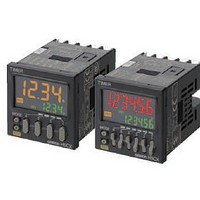
Stopwatches / Timers SCREW TERM RLY OUT Multi-Function
Manufacturer
Omron
Series
H5CXr
Datasheet
1.Y92P-CXT4B.pdf
(44 pages)
Specifications of H5CX-AD-N AC24/DC12-24
Timing Range
0.001 s to 9999 Hrs
Supply Voltage
12 V to 24 V
Current Rating (max)
100 mA
Display Type
4 Digit LCD Backlight
Product
Digital Timer
Termination Style
Screw
Time Range
0.001s-9999hrs
Power Consumption
2.4W
Reset Time
20ms
Character Size
11.5mm
Mounting Type
Panel
Time Range Min
0.001s
Supply Voltage Min
12V
Connector Type
Screw Terminal
Relay Type
Integrated
Function
Programmable (Multi-Function)
Circuit
SPDT (1 Form C)
Delay Time
0.001 Sec ~ 9999 Hrs
Output Type
Mechanical Relay
Contact Rating @ Voltage
5A @ 250VAC
Voltage - Supply
12 ~ 24VDC, 24VAC
Timing Adjustment Method
DIP Switches
Timing Initiate Method
Input Voltage, Trigger Signal
No. Of Digits / Alpha
4
Rohs Compliant
Yes
Lead Free Status / RoHS Status
Lead free / RoHS Compliant
For Use With
PNP/NPN
Lead Free Status / RoHS Status
Lead free / RoHS Compliant, Lead free / RoHS Compliant


Mode b: Repeat cycle 1 (Timer resets when power comes ON.)
Basic operation
* Start signal input is disabled during timing.
Timing starts when the start signal goes ON.
The status of the control output is reversed when time
is up (OFF at start).
While the start signal is ON, the timer starts when the
power comes ON or when the reset input goes OFF.
Note: Normal output operation will not be possible if
* Start signal input is disabled during timing.
Timing starts when the start signal goes ON.
The control output is turned ON when time is up.
While the start signal is ON, the timer starts when the
power comes ON or when the reset input goes OFF.
Note: Normal output operation will not be possible if
Mode b-1: Repeat cycle 2 (Timer does not reset when power comes ON.)
Basic operation
* Start signal input is disabled during timing.
Timing starts when the start signal goes ON.
The status of the control output is reversed when time
is up (OFF at start).
While the start signal is ON, the timer starts when the
power comes ON or when the reset input goes OFF.
Note: Normal output operation will not be possible if
* Start signal input is disabled during timing.
Timing starts when the start signal goes ON.
The control output is turned ON when time is up.
While the start signal is ON, the timer starts when the
power comes ON or when the reset input goes OFF.
Note: Normal output operation will not be possible if
Start signal
Start signal
Start signal
Start signal
Output
Output
Output
Output
Power
Power
Power
Power
input
input
input
input
the set time is too short.
Set the value to at least 100 ms (contact
output type).
the set time is too short.
Set the value to at least 100 ms (contact
output type).
the set time is too short.
Set the value to at least 100 ms (contact
output type).
the set time is too short.
Set the value to at least 100 ms (contact
output type).
*
*
*
*
Timing
Timing
Timing
Timing
Timing Sustained Timing
Timing Sustained Timing
Timing
Timing
Timing
Timing
Timing
Timing
Timing
Timing
Timing
Timing
Detailed operation
Sustained Output
One-shot Output
Detailed operation
Sustained Output
One-shot Output
Control output
Control output
Control output
Control output
Start signal
Start signal
Start signal
Start signal
UP
DOWN
UP
DOWN
UP
DOWN
UP
DOWN
Set value
Set value
Set value
Set value
Set value
Set value
Set value
Set value
Power
Power
Power
Power
Reset
Reset
Reset
Reset
Gate
Gate
Gate
Gate
0
0
0
0
0
0
0
0
t
t
t
t
t
H5CX-A@-N/-L@-N
t
Timer
t
21