MSO3014 Tektronix, MSO3014 Datasheet - Page 14
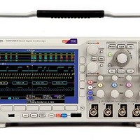
MSO3014
Manufacturer Part Number
MSO3014
Description
Benchtop Oscilloscopes 100MHZ, 2.5GS/S 4+16 CHANNELS
Manufacturer
Tektronix
Type
Mixed Signalr
Datasheet
1.MSO3034.pdf
(18 pages)
Specifications of MSO3014
Equipment Type
Oscilloscope
Sampling Rate
2.5 GS/s
Bandwidth
100 MHz
Display Type
WVGA Color 9 in
Brand/series
MSO3000 Series
Configuration
Bench/Portable
Memory
5 Mpts
Number Of Channels
4 Analog + 16 Digital
Sample Rate
2.5 GS/s analog, 500 MS/s dogtial main, 8.25 GS/s digital MagniVu
Record Length
5 M Points
Input Impedence
50Ω, 75Ω, 1MΩ
Waveform Capture Rate
50,000 wfm/s
Power Analysis
Optional
Standard I/o
(2) USB Host, USB Device, LAN, Video
Display
9.0 inch WVGA
Lead Free Status / RoHS Status
Lead free / RoHS Compliant


Data Sheet
Display Characteristics
Characteristic
Display Type
Display Resolution
Waveform Styles
Graticules
Format
Maximum Waveform
Capture Rate
Input/Output Ports
Port
USB 2.0 High-speed
Host Port
USB 2.0 High-speed
Device Port
LAN Port
Video Out Port
Auxiliary Input
Probe Compensator
Output
Trigger Out
Kensington Style
Lock
Power Source
Characteristic
Power Source
Voltage
Power Source
Frequency
Power Consumption
Optional TekVPI
External Power
Supply*
*
14
1
Required when total oscilloscope probe power usage exceeds 20 W.
www.tektronix.com
1
®
Description
9 in. (228.6 mm) wide format liquid crystal TFT
color display.
800 horizontal × 480 vertical pixels (WVGA).
Vectors, Dots, Variable Persistence, Infinite
Persistence.
Full, Grid, Cross Hair, Frame, IRE and mV.
YT and XY.
>50,000 wfm/s.
Description
Supports USB mass storage devices, printers, and
keyboards. One port available on rear panel and
one on front panel.
Rear-panel connector allows for
communication/control of oscilloscope through
USBTMC or GPIB with a TEK-USB-488, and direct
printing to all PictBridge-compatible printers.
RJ-45 connector, supports 10/100Base-T.
DB-15 female connector, connect to show the
oscilloscope display on an external monitor or
projector.
Front-panel BNC connector. Input Impedance
1 MΩ. Max input 300 V
±450 V.
Front-panel pins
Amplitude: 2.5 V
Frequency: 1 kHz
Rear-panel BNC connector, provides a
negative-polarity pulse when the oscilloscope
triggers.
Rear-panel security slot connects to standard
Kensington-style lock.
Description
85 to 265 V ±10%
45 to 440 Hz (85 to 265 V)
120 W maximum
Output Voltage: 12 V
Output Current: 5 A
Power Consumption: 50 W
RMS
CAT II with peaks ≤
Physical Characteristics
Environmental
Characteristic
Temperature
Humidity
Altitude
Random Vibration
Regulatory
Dimensions
Height
Width
Depth
Weight
Net
Shipping
Rackmount Configuration
Cooling Clearance
Operating
Nonoperating
Operating
Nonoperating
Operating
Nonoperating
Operating
Nonoperating
Electromagnetic
Compatibility
Safety
Description
0 ºC to +50 ºC
-40 ºC to +71 ºC
High: 30 ºC to 50 ºC, 5% to 45% Relative Humidity
Low: 0 ºC to 30 ºC, 5% to 95% Relative Humidity
High: 30 ºC to 50 ºC, 5% to 45% Relative Humidity
Low: 0 ºC to 30 ºC, 5% to 95% Relative Humidity
3,000 meters (9,843 feet)
12,000 meters (39,370 feet)
0.31 G
3 axes, 30 minutes total
2.46 G
3 axes, 30 minutes total
EC Council Directive 2004/108/EC
UL61010-1:2004; CAN/CSA C22.2 No.
61010.1-04;
EN61010-1:2001; IEC61010-1:2001
2 in. (51 mm) required on left side and rear
RMS
RMS
from 5 to 500 Hz, 10 minutes each axis,
from 5 to 500 Hz, 10 minutes each axis,
203.2
416.6
147.3
mm
4.17
8.62
kg
of instrument
5U
16.4
in.
5.8
lb.
9.2
19
8