E32-D24 Omron, E32-D24 Datasheet - Page 7
E32-D24
Manufacturer Part Number
E32-D24
Description
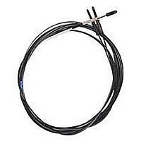
Fiber Optic Sensors SIDE VIEW CABLE
Manufacturer
Omron
Type
Fiber Optic Cablesr
Specifications of E32-D24
Cable Type
Fiber Optic Diffuse Side Beam
Features
Set-Mode blinking light source aids alignment
Sensing Method
Light
Sensing Distance
15.24 mm
Sensor Output
Analog
Sensor Housing
Barrel
Sensor Input
Fiber Optic
Sensing Range Max
40mm
Switch Terminals
Cable
Sensing Mode
Diffuse
Fiber Optic Sensor Type
Side Sensing
Rohs Compliant
Yes
Lead Free Status / RoHS Status
Lead free / RoHS Compliant
Lead Free Status / RoHS Status
Lead free / RoHS Compliant, Lead free / RoHS Compliant


ì¡í²ÅEÉAÉvÉäÉPÅ[ÉVÉáÉì
Standard Models
Fiber Length
■Applicable Models
■Model Number Used for Ordering
Sleeve Length and Bends
■Applicable Models
Fiber Customization Service
Standard models
Flexible Break-resistant Models
Standard model number + Fiber length
Fiber length: 0.3 m, 0.5 m, or any length from
1 to 20 m (in 1-m units)
E32-TC200B/E32-TC200F
E32-DC200B/E32-DC200F
The E32-DC200B cannot be bent.
Fluorine Coating
• Fiber degradation due to oil is prevented using a fluo-
• Free cutting is possible with cutter provided.
roresin coating.
Oil is blocked!
(Fiber Length, Sleeve
Length, and Bends)
Model Numbers Incorporating the Bending Radius, R, and Dimensions L1 and L2
Specifying L1 Only
This customization/delivery service applies to standard models. It is
aimed at reducing industrial waste and simplifying the installation
procedure.
■ Fiber Length vs. Sensing Distance
■ Model Number Used When Changing Only the Sleeve Length
■ Model Number Used When Changing the Sleeve Length and Bends
Bending
R5
R7.5
R10
R12.5
radius
Through-beam Fiber Units
(Fiber length of 2 m corresponds to
100%.)
100
80
60
40
20
0
L1 (±1)
10
15
12.5
17.5
15
20
17.5
22.5
2
5
*1: Insert "T" for Through-beam Fiber Units and "D" for Fiber Units with Reflective Sensors.
*2: Insert the "B" or "F" that appears at the end of the original model number.
*3: Insert "50" if the total length is 50 mm. The total length must not exceed 120 mm.
L1
■ Feature: Fluorine Coating
Fluororesin is used as the sheath material to prevent fi-
ber degradation resulting from oil adhesion.
Note: The tip of the head is not chemical-resistant.
■ Ratings/Characteristics
Model: E32- *1C200 *2 -S*3
E32- *1 C200 *2 -S *3 A1
E32- *1 C200 *2 -S *3 A2
E32- *1 C200 *2 -S *3 B1
E32- *1 C200 *2 -S *3 B2
E32- *1 C200 *2 -S *3 C1
E32- *1 C200 *2 -S *3 C2
E32- *1 C200 *2 -S *3 D1
E32- *1 C200 *2 -S *3 D2
Min. sensing ob-
ject
Min. bending ra-
dius
Ambient temper-
ature range
Fiber material
10
R
Total length
Model number
L
15
Fiber length (m)
20
(Units: mm)
0.005-mm dia.
4 mm
−40°C to 70°C (with no icing or condensation)
Plastic
Specifying L2 Only
Fiber Units with Reflective Sensors
(Fiber length of 2 m corresponds to
100%.)
R5
R7.5
R10
R12.5
L2
Bending
radius
(Cross section)
100
80
60
40
20
0
2
L2 (±1)
5
10
7.5
17.5
10
20
12.5
22.5
Total length
5
Fluororesin coating
10
R
E32- *1 C200 *2 -S *3 A3
E32- *1 C200 *2 -S *3 A4
E32- *1 C200 *2 -S *3 B3
E32- *1 C200 *2 -S *3 B4
E32- *1 C200 *2 -S *3 C3
E32- *1 C200 *2 -S *3 C4
E32- *1 C200 *2 -S *3 D3
E32- *1 C200 *2 -S *3 D4
15
Model number
Fiber length (m)
20
(Units: mm)
U
7
Related parts for E32-D24
Image
Part Number
Description
Manufacturer
Datasheet
Request
R

Part Number:
Description:
Fiber Optic Sensors 1.5mm DIA FLEXIBLE D IFFUSE FO
Manufacturer:
Omron
Datasheet:
Part Number:
Description:
Fiber Optic Sensors HIGHFLEX HIGHTEMP D IFFUSE R10
Manufacturer:
Omron
Datasheet:
Part Number:
Description:
E32-R21 Retroreflective Type Fiber-Optic Cable, M6 Screw Head Retroflective Beam Fiber Cable Suitable For Transparent Object Detection
Manufacturer:
Omron
Datasheet:
Part Number:
Description:
SEP, STRAT, 3.5CM SD
Manufacturer:
Omron
Datasheet:

Part Number:
Description:
5 METER CABLE LENGTH
Manufacturer:
Omron
Datasheet:
Part Number:
Description:
TB,Narrow Vision Field 3.0 Deg
Manufacturer:
Omron
Datasheet:

Part Number:
Description:
G6S-2GLow Signal Relay
Manufacturer:
Omron Corporation
Datasheet:
Part Number:
Description:
Compact, Low-cost, SSR Switching 5 to 20 A
Manufacturer:
Omron Corporation
Datasheet:
Part Number:
Description:
Manufacturer:
Omron Corporation
Datasheet: