E32-D24 Omron, E32-D24 Datasheet - Page 55
E32-D24
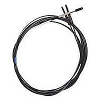
Manufacturer Part Number
E32-D24
Description
Fiber Optic Sensors SIDE VIEW CABLE
Manufacturer
Omron
Type
Fiber Optic Cablesr
Specifications of E32-D24
Cable Type
Fiber Optic Diffuse Side Beam
Features
Set-Mode blinking light source aids alignment
Sensing Method
Light
Sensing Distance
15.24 mm
Sensor Output
Analog
Sensor Housing
Barrel
Sensor Input
Fiber Optic
Sensing Range Max
40mm
Switch Terminals
Cable
Sensing Mode
Diffuse
Fiber Optic Sensor Type
Side Sensing
Rohs Compliant
Yes
Lead Free Status / RoHS Status
Lead free / RoHS Compliant
Lead Free Status / RoHS Status
Lead free / RoHS Compliant, Lead free / RoHS Compliant


E32-L86
E32-L64
E32-A10
Mounting hole dimensions (recommended)
<Screw-mounting Model>
Example: Head size of E32-TC200 is M4. Open the mounting holes with 4 to 4.5 dia.
<Cylindrical Model>
Example: Head size of E32-T22 is 2 dia.. Open the mounting holes with 2.2 to 2.4 dia.
Outer diameter of
fiber unit
F dimensions
Outer diameter of
fiber unit
F dimensions
Special-beam Models
Outer diameter of
fiber unit
F dimensions
Two, 4 dia.
Mounting holes Two, 3.4 dia.
Two, 6.3 dia. countersinks
Sensing surface
16.5
16.5
R25
R25
R25
4
Sensing surface
5
Sensing surface
1.2
8
3
4
3.5 dia.
3.5
5.5
5.5
8.9
1 dia.
+0.5
+0.5
8.4
0
0
M3
+0.2
0
Two, 4 dia.
dia.
dia.
18
18
dia. 1.7
8.9 18
Convergent-reflective Models
4
18
10.7
14
F
4.5
4
6
1.5 dia.
25
25
2
18
4 dia.
+0.5
21
21
0
M4
+0.2
+0.5
0
0
7
dia.
6.5
22.5
dia. 2.2
dia. 5.5
19
33.5
33.5
Mounting holes Two, 3.2 dia.
Two, 6.2 dia. countersinks
27
(SUS304)
(ABS)
7
6
6
2 dia.
5 dia.
+0.5
0
M6
+0.2
+0.5
0
0
(SUS304)
A
dia.
Two, 3.2 dia. mounting holes with
two, 6 dia. countersinks on one side
dia. 3.2
dia. 6.5
(45)
2,000
A
Two, 2.8 dia. flexible tubes (SUS304)
14 dia.
2,000
2,000
Two, 2.9 dia. flexible tubes
(stainless steel)
(Unit:mm)
(Unit:mm)
3 dia.
6 dia.
M14
+0.2
+0.5
+1
Two, 2.2 dia.
0
0
0
Model display tube: 3.3 dia.
dia.
dia.
5 (max.)
4 dia.
30(B)
4 dia.
Minimum bending radius
25(B)
(except E32-C11N, E32-C31N
Flexible
(E32-C11N, E32-C31N,
*
Flexible
and E32-CC200)
E32-CC200R)
2.2 dia.
Cutting free (Cutter provided)
Type
R10
R25
R30
R35
R40
Note: The maximum allowable temperatures are 300°C for
Break-resistant
Break-resistant
R4
Mounting holes
Mounting holes
section A and 110°C for section B (section inserted into
the Amplifier Unit).
2-M3
7±0.1
Minimum bending radius
Sensing
6.5±0.1
head
Note: The maximum allowable temperatures
2-M3
Minimum bending
for sections A and B are 200°C and
110°C, respectively. The section inserted
into the Amplifier Unit (indicated by *),
however, must stay within the Amplifier
Unit's operating temperature range.
A
unbendable
Fluororesin coating
Fluororesin coating
radius
B
10
25
30
35
40
A
1
4
4
unbendable
R@
R@
Standard
10
10
10
10
10
10
B
0
0
Standard
(Unit:mm)
55
Related parts for E32-D24
Image
Part Number
Description
Manufacturer
Datasheet
Request
R

Part Number:
Description:
Fiber Optic Sensors 1.5mm DIA FLEXIBLE D IFFUSE FO
Manufacturer:
Omron
Datasheet:
Part Number:
Description:
Fiber Optic Sensors HIGHFLEX HIGHTEMP D IFFUSE R10
Manufacturer:
Omron
Datasheet:
Part Number:
Description:
E32-R21 Retroreflective Type Fiber-Optic Cable, M6 Screw Head Retroflective Beam Fiber Cable Suitable For Transparent Object Detection
Manufacturer:
Omron
Datasheet:
Part Number:
Description:
SEP, STRAT, 3.5CM SD
Manufacturer:
Omron
Datasheet:

Part Number:
Description:
5 METER CABLE LENGTH
Manufacturer:
Omron
Datasheet:
Part Number:
Description:
TB,Narrow Vision Field 3.0 Deg
Manufacturer:
Omron
Datasheet:

Part Number:
Description:
G6S-2GLow Signal Relay
Manufacturer:
Omron Corporation
Datasheet:
Part Number:
Description:
Compact, Low-cost, SSR Switching 5 to 20 A
Manufacturer:
Omron Corporation
Datasheet:
Part Number:
Description:
Manufacturer:
Omron Corporation
Datasheet: