RF100-5 TELEDYNE, RF100-5 Datasheet - Page 2
RF100-5
Manufacturer Part Number
RF100-5
Description
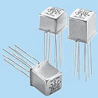
RF (Radio Frequency) Relays 5V DC-6GHz .10W
Manufacturer
TELEDYNE
Type
High Reliability Ultra Miniature Relayr
Series
RF100/103r
Specifications of RF100-5
Coil Resistance
50 Ohms
Frequency
4 GHz
Contact Form
DPDT
Coil Voltage
5 VDC
Power Consumption
369 mW to 500 mW
Termination Style
PCB
Coil Voltage Vdc Nom
5V
Coil Type
DC Coil
Relay Mounting
PC Board
External Width
9.53mm
External Depth
9.53mm
Contact Configuration
DPDT
Contact Current Dc Max
50µA
Contact
RoHS Compliant
Contact Arrangement
DPDT
Dc Coil Voltage
5 V
Coil Current
100 mA
Mounting
Through Hole
Brand/series
RF100 Series
Capacitance
0.4 pF
Current, Rating
50 μA
Diameter, Lead
0.017 in.
Function
Frequency (RF)
Height
0.290 in.
Length, Lead
0.75 in.
Mounting Type
PCB
Number Of Pins
8
Relay Type
Electro Mechanical
Resistance, Coil
50 Ohms
Resistance, Contact
0.100 Ohms
Temperature, Operating
-55 to +85 °C
Termination
Leadwires
Voltage, Control
5 VDC
Voltage, Rating
0.050 V
External Height
7.37mm
Rohs Compliant
Yes
Lead Free Status / RoHS Status
Lead free / RoHS Compliant
Lead Free Status / RoHS Status
Lead free / RoHS Compliant


©2003 TELEDYNE RELAYS
SERIES RF100 AND RF103
TYPICAL RF CHARACTERISTICS (See RF Notes)
RF NOTES
1. Test conditions:
2. Data presented herein represents typical characteristics and is not intended for use as specification limits.
3. Data is per pole, except for pole-to-pole data.
4. Data is the average from readings taken on all open contacts.
5. Data is the average from readings taken on poles with coil energized and de-energized.
6. Data is the average from readings taken on all closed contacts.
7. Test fixture effect de-embedded from frequency and time response data.
-0.2
-0.4
-0.6
-0.8
-1.2
-1.4
-1.6
-1.8
-20
-30
-40
-50
-60
-1
0
0
0
500
500
1000
1000
Isolation Across Contacts (RF Note 4)
1500
1500
a. Fixture: .031" copper clad, reinforced PTFE, RT/duroid
b. Room ambient temperature.
c. Terminals not tested were terminated with 50-ohm load.
d. Contact signal level: –10 dBm.
e. No. of test samples: 2.
Insertion Loss (RF Note 6)
2000
2000
registered trademark of Rogers Corporation.)
Frequency (MHz)
Frequency (MHz)
2500
2500
3000
3000
SPECIFICATIONS ARE SUBJECT TO CHANGE WITHOUT NOTICE
-0.1
1.1
0.9
0.7
0.5
0.3
0.1
3500
3500
-100
4000
4000
0
4500
4500
100
5000
5000
RF100 Time Response (RF Note 6)
www.teledynerelays.com
81.1ps propagation delay time
58.1ps pulse rise time
200
5500
5500
37ps reference
90%
10%
6000
6000
300
Time (ps)
400
3.00
2.60
2.20
1.80
1.40
1.00
-20
-30
-40
-50
-60
0
0
500
500
500
600
®
1000 1500 2000 2500 3000 3500 4000 4500 5000 5500 6000
1000
6002 with SMA connectors. (RT/duroid
700
Isolation Pole to Pole (RF Note 5)
1500
800
2000
VSWR (RF Note 6)
Frequency (MHz)
Frequency (MHz)
2500
900
3000
3500
4000
RF100 RF103 Page 2
4500
RF100 RF103/1203/Q1
5000
®
is a
5500
6000
Related parts for RF100-5
Image
Part Number
Description
Manufacturer
Datasheet
Request
R

Part Number:
Description:
RELAY, 12V, HIGH RELIABILITY
Manufacturer:
TELEDYNE
Datasheet:

Part Number:
Description:
RF (Radio Frequency) Relays 5V DC-1GHz .15W
Manufacturer:
TELEDYNE
Datasheet:

Part Number:
Description:
RF (Radio Frequency) Relays 5V DC-6GHz 10W HI SENSITIVITY
Manufacturer:
TELEDYNE
Datasheet:
Part Number:
Description:
RF (Radio Frequency) Relays 12V DC-1GHz .15W w/diode
Manufacturer:
TELEDYNE
Datasheet:
Part Number:
Description:
RF (Radio Frequency) Relays 12V DC-1GHz .15W
Manufacturer:
TELEDYNE
Datasheet:

Part Number:
Description:
RF (Radio Frequency) Relays 5V DC-6GHz .10W
Manufacturer:
TELEDYNE
Datasheet:

Part Number:
Description:
RF (Radio Frequency) Relays 26V DC-1GHz .15W
Manufacturer:
TELEDYNE
Datasheet:
Part Number:
Description:
RF (Radio Frequency) Relays 5V DC-6GHz .10W hi sensitivity
Manufacturer:
TELEDYNE
Datasheet:

Part Number:
Description:
RF (Radio Frequency) Relays 5V DC-6GHz .15W
Manufacturer:
TELEDYNE
Datasheet:
Part Number:
Description:
RF (Radio Frequency) Relays 5V DC-1GHz .15W w/diode
Manufacturer:
TELEDYNE
Datasheet:
