RF100-12 TELEDYNE, RF100-12 Datasheet
RF100-12
Specifications of RF100-12


Related parts for RF100-12


RF100-12 Summary of contents
Page 1
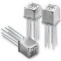
... PERFORMANCE FEATURES The ultraminiature RF100 and RF103 relays are designed to provide improved RF signal repeatability over the frequency range. These relays are highly suitable for use in attenuator and other RF circuits, the RF100 and RF103 feature: • High repeatability. • Broader bandwidth. ...
Page 2
... RF100 Time Response (RF Note 6) 90% 37ps reference 81.1ps propagation delay time 58.1ps pulse rise time 10% 0 100 200 300 400 500 600 Time (ps) ® 6002 with SMA connectors. (RT/duroid www ...
Page 3
... Test performed at room ambient temperature. d. Contact signal level: 20 dBm. 2. Data presented herein represents typical characteristics and is not intended for use as specification limits. 3. Insertion loss repeatability measured over frequency range from .3 MHz to 4 GHz. RF100 RF103 Page 3 SPECIFICATIONS ARE SUBJECT TO CHANGE WITHOUT NOTICE Normally Open 100 ...
Page 4
... REF. .035 (.89) 0.100 0.010 REF. (2.54 0.25) EXTERNAL DIMENSIONS www.teledynerelays.com DPDT Continuous 4.0 ms. max. 6.0 ms. max. 3.0 ms. max. 3.0 ms. max. 0.4 pF typical RF100-12 RF103-12 12.0 390 800 9.0 .375 (9.53) SQ. MAX. .335 (8.51) SQ. MAX. H DIMENSION MAX. .290 RF100 H (7 ...
Page 5
... MAX ER431, ER431D, ER431DD RF311 RF331 172, 172D ER114, ER114D, ER114DD, Dim H J114, J114D, J114DD MAX ER134, ER134D, ER134DD, J134, J134D, J134DD RF100 RF103 122C, A152 ER116C, J116C H Dim MAX ER136C, J136C RF180 A150 SPECIFICATIONS SUBJECT TO CHANGE WITHOUT NOTICE Dim. H Max. ...
Page 6
... Dim H MAX .014 [0.36] (REF) .370 [9.4] MIN +44 (0) 1236 453124 • www.teledyne-europe.com For use with the following: ER411T, J411T, ER412, ER412D ER412DD, J412, J412D, J412DD ER412T, J412T 712, 712D, 712TN ER431T, J431T, ER432, ER432D ER432DD, J432, J432D, J432DD ER432T, J432T ...
Page 7
... POSITION "U" POSITION (ER116C and ER136C only) Centigrid® Relays: RF100, RF103, ER114, ER134, 172 NOTES 1. Terminal views shown 2. Dimensions are in inches (mm) 3. Tolerances: ± .010 (±.25) unless otherwise speci¿ Ground pin positions are within .015 (0.38) dia. of true position 5 ...