P7S-14F-END-DC24 Omron, P7S-14F-END-DC24 Datasheet - Page 5
P7S-14F-END-DC24
Manufacturer Part Number
P7S-14F-END-DC24
Description
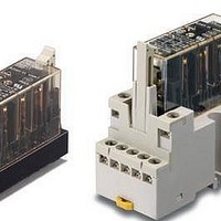
Relay Sockets & Hardware G7 RELAY TRACK MT SOCKET
Manufacturer
Omron
Datasheet
1.P7S-14F-END-DC24.pdf
(6 pages)
Specifications of P7S-14F-END-DC24
Associated Relay Series
G7S
Mounting Style
Panel
Accessory Type
Track Mounting Sockets
Termination Style
SMD/SMT
Lead Free Status / RoHS Status
Lead free / RoHS Compliant


Certified Standards
Safety Precautions
Refer to the “Precautions for All Relays” and “Precautions for All Relays with Forcibly Guided Contacts”.
Wiring
Cleaning
The G7S is not of enclosed construction. Therefore, do not wash the
G7S with water or detergent.
• EN Standards, VDE Certified
• UL standard UL508 Industrial Control Devices
• CSA standard CSA C22.2 No. 14 Industrial Control Devices
• Use one of the following wires to connect to the P7S-14F-END.
• Tighten each screw of the P7S-14F-END to a torque of 0.78
• Refer to the internal connections diagram of the G9S Safety Relay
• Wire the terminals correctly with no mistakes in coil polarity,
EN61810-1 (Electromechanical non-specified time all-or-nothing
relays)
EN50205 (Relays with forcibly guided (linked) contacts)
to 0.98 N·m.
Unit for an application example of the G7S.
otherwise the G7S will not operate.
Stranded wire: 0.75 to 1.5 mm
Solid wire:
Precautions for Correct Use
1.0 to 1.5 mm
2
2
Forcibly Guided Contacts
If an NO contact becomes welded, all NC contacts will maintain a
minimum distance of 0.5 mm when the coil is not energized. Likewise
if an NC contact becomes welded, all NO contacts will maintain a
minimum distance of 0.5 mm when the coil is energized.
(from EN50205)
G7S
5
Related parts for P7S-14F-END-DC24
Image
Part Number
Description
Manufacturer
Datasheet
Request
R


Part Number:
Description:
Contact OSTI
Manufacturer:
Omron
Datasheet:

Part Number:
Description:
G6S-2GLow Signal Relay
Manufacturer:
Omron Corporation
Datasheet:
Part Number:
Description:
Compact, Low-cost, SSR Switching 5 to 20 A
Manufacturer:
Omron Corporation
Datasheet:
Part Number:
Description:
Manufacturer:
Omron Corporation
Datasheet:
Part Number:
Description:
Manufacturer:
Omron Corporation
Datasheet:
Part Number:
Description:
Manufacturer:
Omron Corporation
Datasheet:
Part Number:
Description:
Manufacturer:
Omron Corporation
Datasheet:
Part Number:
Description:
Manufacturer:
Omron Corporation
Datasheet:
Part Number:
Description:
Manufacturer:
Omron Corporation
Datasheet: