P7S-14F-END-DC24 Omron, P7S-14F-END-DC24 Datasheet - Page 2
P7S-14F-END-DC24
Manufacturer Part Number
P7S-14F-END-DC24
Description
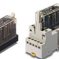
Relay Sockets & Hardware G7 RELAY TRACK MT SOCKET
Manufacturer
Omron
Datasheet
1.P7S-14F-END-DC24.pdf
(6 pages)
Specifications of P7S-14F-END-DC24
Associated Relay Series
G7S
Mounting Style
Panel
Accessory Type
Track Mounting Sockets
Termination Style
SMD/SMT
Lead Free Status / RoHS Status
Lead free / RoHS Compliant


Specifications
Ratings
Coil
Note: 1. The rated current and coil resistance are measured at a coil temperature of 23°C with tolerances of ±15%.
Contacts
Characteristics of Sockets
Note: Use the P7S-14F-END in the ambient humidity range of 35 to 85%.
* The insulation resistance was measured with a 500-VDC megohmmeter at the same locations as the dielectric strength was measured.
Characteristics
Note: The above values are initial values.
*1. Measurement conditions: 5 VDC, 10 mA, voltage drops.
*2. Measurement conditions: Rated voltage operation
*3. The insulation resistance was measured with a 500-VDC megohmmeter at the same locations as the dielectric strength was measured.
*4. The durability is for an ambient temperature of 15 to 35°C and an ambient humidity of 25% to 75%.
*5. The failure rate is based on an operating frequency of 60 operations/min.
Rated
voltage
Item
Rated load
Rated carry current
Maximum switching voltage
Maximum switching current
Contact resistance *1
Operating time *2
Release time *2
Maximum operating
frequency
Insulation resistance *3
Dielectric strength
Vibration
resistance
Shock resistance
Durability *4
Failure rate (P level) (reference value *5) 5 VDC, 1 mA
Ambient operating temperature
Ambient operating humidity
Weight
Ambient operating temperature: 23°C
Contact bounce time is not included.
24 VDC
P7S-14@
2. Performance characteristics are based on a coil temperature of 23°C.
3. The maximum voltage is based on an ambient operating temperature of 23°C maximum.
Model
Item
Rated current
Mechanical
Rated load
Destruction
Malfunction
Destruction
Malfunction
Mechanical
Electrical
(mA)
Continuous current
30
10 A
Load
Coil resistance
800
100 mΩ max.
50 ms max.
50 ms max.
18,000 operations/h
1,800 operations/h
100 MΩ min.
2,500 VAC, 50/60 Hz for 1 min. (1,500 VAC between contacts of same polarity)
10 to 55 to 10 Hz, 0.75-mm single amplitude (1.5-mm double amplitude)
10 to 55 to 10 Hz, 0.375-mm single amplitude (0.75-mm double amplitude)
1,000 m/s
100 m/s
10,000,000 operations min. (at approx. 18,000 operations/h)
100,000 operations min. (at the rated load and approx. 1,800 operations/h)
–25 to 70°C (with no icing or condensation)
5% to 85%
Approx. 65 g
(Ω)
2
2,000 VAC for 1 min. between terminals
2
240 VAC: 3 A, 24 VDC: 3 A
Must operate
Resistive load
voltage (V)
80% max.
Dielectric strength
Must release
voltage (V)
10% min.
250 VAC, 24 VDC
6 A
6 A
Inductive load (cos φ = 0.4, L/R = 7 ms)
Max. voltage
240 VAC: 3 A, 24 VDC: 1 A
110%
(V)
Insulation resistance
1,000 MΩ min. *
Power consumption
Approx. 0.8
(W)
G7S
2
Related parts for P7S-14F-END-DC24
Image
Part Number
Description
Manufacturer
Datasheet
Request
R


Part Number:
Description:
Contact OSTI
Manufacturer:
Omron
Datasheet:

Part Number:
Description:
G6S-2GLow Signal Relay
Manufacturer:
Omron Corporation
Datasheet:
Part Number:
Description:
Compact, Low-cost, SSR Switching 5 to 20 A
Manufacturer:
Omron Corporation
Datasheet:
Part Number:
Description:
Manufacturer:
Omron Corporation
Datasheet:
Part Number:
Description:
Manufacturer:
Omron Corporation
Datasheet:
Part Number:
Description:
Manufacturer:
Omron Corporation
Datasheet:
Part Number:
Description:
Manufacturer:
Omron Corporation
Datasheet:
Part Number:
Description:
Manufacturer:
Omron Corporation
Datasheet:
Part Number:
Description:
Manufacturer:
Omron Corporation
Datasheet: