G6L-1P-DC5 Omron, G6L-1P-DC5 Datasheet - Page 7
G6L-1P-DC5
Manufacturer Part Number
G6L-1P-DC5
Description
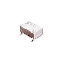
Low Signal Relays - PCB LO PROF SPST 5VDC
Manufacturer
Omron
Series
G6Lr
Specifications of G6L-1P-DC5
Coil Type
Non-Latching
Coil Current
36 mA
Contact Form
1 Form C
Coil Voltage
5 VDC
Power Consumption
180 mW
Termination Style
Solder Pin
Maximum Switching Current
1 A
Contact Rating
0.3 A at 125 VAC, 1 A at 24 VDC
Contact Configuration
SPST-NO
Contact Current Max
1A
Contact Voltage Ac Nom
125V
Contact Voltage Dc Nom
24V
Coil Voltage Vdc Nom
5V
Current, Rating
0.3⁄1 AAC⁄ADC
Dielectric Rating
1000 VAC @ 50⁄60 Hz for 1 Minute (Coil and Contacts), 750 VAC @ 50⁄60 Hz for 1 Minute (Contacts of Same Poles)
Dimensions
10.6 mm L x 7 mm W x 3.8 mm H
Function
General Purpose
Material, Contact
Ag (Au-Clad)
Mounting Type
PCB
Number Of Pins
4
Relay Type
Electro Mechanical
Standards
UL, CSA, FCC, RoHS
Temperature, Operating, Maximum
70 °C
Temperature, Operating, Minimum
-40 °C
Termination
Through Hole
Voltage, Control
5 VDC
Voltage, Rating
125 VAC
Lead Free Status / RoHS Status
Lead free / RoHS Compliant
Lead Free Status / RoHS Status
Lead free / RoHS Compliant, Lead free / RoHS Compliant
Other names
5DC 5DC, G6L-1P G6L1P5DC,
Available stocks
Company
Part Number
Manufacturer
Quantity
Price


Recommended Soldering Method
■ Temperature Profile According to IRS
When performing reflow-soldering, check the profile on an actual
device after setting the temperature condition so that the tempera-
tures at the relay terminals and the upper surface of the case do not
exceed the limits specified in the following tables.
Mounting Solder: Lead Based
Mounting Solder: Lead-free
■ Approved Standards
UL Recognized (File No. E41515) / CSA Certified (File No. LR31928) - - Ambient Temp. = 40°C
Measuring
position
Terminal
Upper surface
of case
Measuring
position
Terminal
Upper surface
of case
SPST-NO
Contact form
Item
Item
T4
T3
T2
T1
150°C to 180°C,
120 s max.
——
150°C to 180°C,
120 s max.
——
(T1 to T2, t
(T1 to T2, t
Preheating
Preheating
G6L-1P and G6L-1F: 3 to 24 VDC
1
1
)
)
Preheating
180°C to 200°C,
20 to 30 s
——
230°C,
30 s max.
——
t
1
Soldering
Soldering
(T3, t
(T3, t
Soldering
2
2
)
)
Coil rating
t
2
Time (s)
245°C max.
250°C max.
250°C max.
255°C max.
Peak value
Peak value
(T4)
(T4)
1A at 30 VDC (Resistive)
0.5A at 60 VDC (Resistive)
0.3A at 125 VAC (General Use)
The thickness of cream solder to be applied should be within a range
between 150 and 200 μm on OMRON's recommended PCB pattern.
Visually check that the Relay is properly soldered.
PCB
Correct Soldering
Contact rating
Terminal
Relay
Solder
Land
Low Signal Relay
Incorrect Soldering
6,000
Number of test operations
Insufficient
amount of
solder
G6L
Excessive
amount of
solder
43
Related parts for G6L-1P-DC5
Image
Part Number
Description
Manufacturer
Datasheet
Request
R

Part Number:
Description:
LOW SIGNAL RELAY
Manufacturer:
Omron
Datasheet:
Part Number:
Description:
LOW SIGNAL RELAY
Manufacturer:
Omron
Datasheet:

Part Number:
Description:
Low Signal Relays - PCB LO PROF SPST 12VDC
Manufacturer:
Omron
Datasheet:
Part Number:
Description:
RELAY TELCOM SPST 3VDC PC MNT
Manufacturer:
Omron
Datasheet:
Part Number:
Description:
RELAY TELCOM SPST 4.5VDC PC MNT
Manufacturer:
Omron
Datasheet:
Part Number:
Description:
RELAY TELCOM SPST 24V PCB
Manufacturer:
Omron
Datasheet:

Part Number:
Description:
RELAY, PCB, SPNO, 24VDC
Manufacturer:
Omron
Datasheet:
Part Number:
Description:
RELAY, PCB, SPNO, 3VDC
Manufacturer:
Omron
Datasheet:
Part Number:
Description:
RELAY, PCB, SPNO, 5VDC
Manufacturer:
Omron
Datasheet:

Part Number:
Description:
RELAY, SMD, SPNO, 12VDC
Manufacturer:
Omron
Datasheet: