G9EC-1-B-DC24 Omron, G9EC-1-B-DC24 Datasheet
G9EC-1-B-DC24
Specifications of G9EC-1-B-DC24


G9EC-1-B-DC24 Summary of contents
Page 1
... DC Power Relays G9EA/G9EB/G9EC DC Control in a Relay A Leader in Clean Energy with Compact, Quiet, Energy-efficient Designs G9EB G9EA G9EC ...
Page 2
... OMRON has improved on the standard DC circuit that switches using a contactor or circuit-breaker by developing the G9EA/G9EB/G9EC DC Power Relay Series. These Relays enable switching high-voltage and high-capacity loads. The switch's gas-filled construction allows a considerable reduction in the relay switch size, while also lowering the operating noise during load switching ...
Page 3
... V max. (for a carry current of 100 A) 400 VDC 1,000 operations min. 120 VDC 2,500 operations min. --- 30 A 100 150 A (10 min) --- 100 A at 120 VDC (150 times min.) --- DC Power Relays G9EC G9EB G9EC-1(-B) G9EB-1-B Switching/current Switching/current conduction conduction 86 ...
Page 4
... Selection Guide 4 DC Power Relays G9EA G9EA-1(-B) G9EA-1(-B)-CA High-current conduction conduction ) 67 Carries 100 A Low contact resistance when carrying current G9EC G9EB G9EC-1(-B) G9EB-1-B Switching/current Switching/current conduction conduction 86 Largest capacity in series Smallest in series Carries/switches 400-V, Carries/switches 250-V, 200-A loads 25-A loads − ...
Page 5
DC Power Relays (60-A, 100-A Models) G9EA-1 DC Power Relays Capable of Interrupting High-voltage, High-current Loads • A compact relay ( 67 H)) capable of switching 400-V 60-A DC loads. (Capable of ...
Page 6
Specifications ■ Ratings Coil Rated voltage Rated current Coil resistance 28.8 Ω 12 VDC 417 mA 115.2 Ω 24 VDC 208 mA 469.3 Ω 48 VDC 102 mA 695.7 Ω 60 VDC 86.2 mA 1,864 Ω 100 VDC 53.6 mA ...
Page 7
Engineering Data ■ G9EA-1(-B) Switching/Current Conduction Models Maximum Switching Capacity 1,000 500 300 G9EA-1 DC resistive load 100 100 300 500 1,000 Switching voltage (V) Carry Current vs Energizing Time 100,000 ...
Page 8
All G9EA-1 Models Must-operate Voltage and Must-release Voltage Distributions 30 Must-operate voltage Sample: G9EA-1 Number: 35 Must-release voltage 100 Percentage of rated voltage (%) Vibration Resistance 10.0 Sample: G9EA-1 ...
Page 9
Dimensions Note: All units are in millimeters unless otherwise indicated. Models with Screw Terminals G9EA-1-B(-CA ...
Page 10
Options Terminal Cover P9EA-C DIN Track Adapter P9EA Power Relays (60-A, 100-A Models) 17* 31 13. 17* 17 Dimensions of cutouts for wiring. Two, M5 61± 88 0.1 24± 0 G9EA-1 ...
Page 11
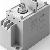
... Note: 1. Two M8 nuts are provided for the contact terminal connection. 2. Two M3.5 screws are provided for the coil terminal connection. Terminals Contact form Contact terminals Screw terminals SPST-NO (See note 1.) DC Power Relays (200-A Models) Coil rated voltage Model 12 VDC G9EC-1-B 24 VDC G9EC-1 48 VDC 60 VDC 100 VDC G9EC-1 11 ...
Page 12
... A at 400 VDC (10 times) 700 A at 400 VDC (40 times min.) − 200 A at 200 VDC (1,000 times min.) − ° C (with no icing or condensation 85% Approx. 560 g G9EC-1 Maximum voltage voltage (See note 3.) consumption 110% of rated volt- Approx age (at 23°C within 10 minutes) G9EC-1(-B) Power ...
Page 13
... Engineering Data ■ G9EC-1(-B) Switching/Current Conduction Models Maximum Switching Capacity 1,000 500 300 100 DC resistive load 0.5 0.3 0 100 300 500 1,000 Switching voltage (V) Carry Current vs Energizing Time 100,000 10,000 1,000 100 10 100 300 500 700 1,000 Carry current (A) Electrical Endurance ...
Page 14
... Characteristics were measured after applying vibration at a frequency (single amplitude of 0.75 mm) to the test piece (not energized) for 2 hours each in 3 directions. The percentage rate of change is the average value for all of the samples Shock Resistance 5.0 Sample: G9EC-1 Number: 5 4.0 3.0 2.0 1.0 Must-operate voltage ...
Page 15
... Internal Connections (TOP VIEW) 1(+) 32 44 2(−) 7 Note: Be sure to connect terminals with the correct polarity. Coils do not have polarity. Mounting Hole Dimensions (TOP VIEW) Two 6.5-dia. holes 26.7 1(+) 86.7 68.6 (Terminal height) 10.5 32± 0.1 G9EC-1 8 86± 0.1 8 86± 0.1 15 ...
Page 16
... Options Terminal Cover P9EC Power Relays (200-A Models) 44 Dimensions of cutout for wiring G9EC-1 Note: Be sure to remove the cutouts for wiring that are located in the wiring outlet direction before in- stalling the Terminal Cover. Dimension (mm) Tolerance (mm) ±0 lower ±0 ± higher ...
Page 17
DC Power Relays (25-A Models) G9EB-1 DC Power Relays Capable of Interrupting High-voltage, High-current DC Load • Utilizes a unique gas-filled, fully sealed, non-ceramic construc- tion achieved by using resin with a metal case. This reduces the need for special ...
Page 18
Specifications ■ Ratings Coil Rated voltage Rated current Coil resistance 72 Ω 12 VDC 166.7 mA 288 Ω 24 VDC 83.3 mA 1,152 Ω 48 VDC 41.7 mA 1,800 Ω 60 VDC 33.3 mA 5,000 Ω 100 VDC 20 mA ...
Page 19
Engineering Data ■ G9EB-1-B Switching/Current Conduction Models Maximum Switching Capacity 100 50 DC resistive load 100 300 500 1,000 Switching voltage (V) Carry Current vs Energizing Time 100,000 50,000 30,000 10,000 5,000 ...
Page 20
Vibration Malfunction 1 Sample: G9EB-1-B 12 VDC Number: 5 0.9 Unconfirmed area 0.8 0.7 0.6 0.5 Confirmed area 0.4 0.3 0.2 0 100 Frequency (Hz) Shock Malfunction Z' 2 Unit: m ...
Page 21
Dimensions Note: All units are in millimeters unless otherwise indicated. Screw Terminal Type G9EB-1-B (Mounting hole dimensions) Dimension (mm) Tolerance (mm) ±0 lower ±0 ± higher (Mounting hole dimensions) Two, ...
Page 22
... M5 screws: 1.57 to 2.35 N·m • M4 screws: 0.98 to 1.37 N·m • M3.5 screws: 0.75 to 1.18 N·m 2. The G9EA and G9EC Relays’ contacts have polarity. Be sure to perform connections with the correct polarity. If the contacts are connected with the reverse polarity, the switching characteristics specified in this document cannot be assured ...
Page 23
Common Precautions DC Power Relay 23 ...
Page 24
... To convert millimeters into inches, multiply by 0.03937. To convert grams into ounces, multiply by 0.03527. Cat. No. J144-E1-03 In the interest of product improvement, specifications are subject to change without notice. OMRON RELAY & DEVICES Corporation DC Power Business Promotion Department 1110, Sugi, Yamaga-city, Kumamoto-Pref., 861-0596 Japan Tel: (81)968-44-4641/Fax: (81)968-44-4107 Printed in Japan 0606-0 ...