142-1701-121 Emerson Network Power, 142-1701-121 Datasheet - Page 2
142-1701-121
Manufacturer Part Number
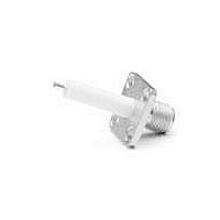
142-1701-121
Description
RF Connectors 4 Hole Flange Mnt JK Recpt;gold
Manufacturer
Emerson Network Power
Datasheet
1.142-1701-121.pdf
(3 pages)
Specifications of 142-1701-121
Body Style
Straight
Cable Type
RG178,RG316,RG58, RG142
Connector Type
Jack
Frequency Range
0 Hz to 18 GHz
Rf Series
SMA
Product
Various Connectors
Gender
Female
Shell Plating
Gold
Impedance
50 Ohms
Maximum Frequency
18 GHz
Lead Free Status / RoHS Status
Lead free / RoHS Compliant


Impedance: 50 ohms
Frequency Range:
VSWR: (f = GHz)
RG-178 cable .............................. 1.20 + .025f
RG-316, LMR-100 cable .............. 1.15 + .02f
RG-58, LMR-195 cable ................ 1.15 + .01f
RG-142 cable ............................... 1.15 + .01f
LMR-200, LMR-240 cable ............ 1.10 + .03f
.086 semi-rigid ............................ 1.07 + .008f
.141 semi-rigid (w/contact) .......... 1.05 + .008f
.141 semi-rigid (w/o contact) ...... 1.035 + .005f
Jack-bulkhead jack adapter and plug-plug adapter ................. 1.05 + .01f
Jack-jack adapter and plug-jack adapter ............................... 1.05 + .005f
Uncabled receptacles, dummy loads .................................................. N/A
Field replaceable (see page 59) ......................................................... N/A
Working Voltage: (Vrms maximum)
Connectors for Cable Type
Dielectric Withstanding Voltage: (VRMS minimum at sea level)
Corona Level: (Volts minimum at 70,000 feet)
Dummy loads ...................................................................................... N/A
Engagement Design: MIL-C-39012, Series SMA
Engagement/Disengagement Force: 2 inch-pounds maximum
Mating Torque: 7 to 10 inch-pounds
Bulkhead Mounting Nut Torque: 15 inch-pounds
Coupling Proof Torque: 15 inch-pounds minimum
Coupling Nut Retention: 60 pounds minimum
Contact Retention:
Temperature Range: - 65°C to + 165°C
Thermal Shock: MIL-STD-202, Method 107, Condition B
Corrosion: MIL-STD-202, Method 101, Condition B
†Avoid user injury due to misapplication. See safety advisory definitions inside front cover.
SMA - 50 Ohm Connectors
Specifications
Dummy loads .......................................................................... 0-2 GHz
Flexible cable connectors ................................................... 0-12.4 GHz
Uncabled receptacles, RA semi-rigid and adapters ........... 0-18.0 GHz
Straight semi-rigid cable connectors and
field replaceable connectors ............................................... 0-26.5 GHz
RG-178 ...................................................................... 170
RG-316; LMR-100, 195, 200 ..................................... 250
RG-58, RG-142, LMR-240, .086 semi-rigid,
.141 semi-rigid with contact and adapters ................. 500
Dummy loads ................................................................................. N/A
Connectors for RG-178 ................................................................... 500
Connectors for RG-316; LMR-100, 195, 200 .................................. 750
Connectors for RG-58, RG-142, LMR-240, .086 semi-rigid,
Connectors for .141 semi-rigid with contact and adapters ............ 1500
Connectors for .141 semi-rigid w/o contact, dummy loads .............. N/A
Connectors for RG-178 ................................................................... 125
Connectors for RG-316; LMR-100, 195, 200 .................................. 190
Connectors for RG-58, RG-142, LMR-240, 086 semi-rigid,
uncabled receptacles, .141 semi-rigid w/o contact .......................... 250
Connectors for .141 semi-rigid with contact and adapters .............. 375
uncabled receptacles, .141 semi-rigid w/o contact ... 335
field replaceable, uncabled receptacles ...................................... 1000
6 lbs. minimum axial force (captivated contacts)
4 inch-ounce minimum torque (uncabled receptacles)
299 Johnson Avenue SW, Waseca, MN 56093 • 800 -247- 8256 • +1 (507) 833-8822 • www.EmersonConnectivity.com
ENVIRONMENTAL RATINGS
Cabled Connectors
Straight
Emerson Network Power Connectivity Solutions
Sea Level 70K Feet
Cabled Connectors
MECHANICAL RATINGS
ELECTRICAL RATINGS
1.20 + .03f
1.15 + .03f
1.15 + .02f
1.15 + .02f
1.10 + .06f
1.18 + .015f
1.15 + .015f
Right Angle
125
85
45
65
(Meets or exceed the applicable paragraph of MIL-C-39012)
Center contact (right angle cabled
Outer contact (all connectors) ........................... 2.0
Braid to body (gold plated connectors) ............. 0.5
Braid to body (nickel plated connectors) ........... 5.0
*N/A where the cable center conductor is used as a contact
RF Leakage: (dB minimum, tested at 2.5 GHz)
RF High Potential Withstanding Voltage: (Vrms minimum, tested at 4
+125°C
Insertion Loss: (dB maximum)
Insulation Resistance: 5000 megohms minimum
Contact Resistance: (milliohms maximum) Initial
Center contact (straight cabled connectors
and 7 MHz)
Power Rating (Dummy Load): 0.5 watt @ + 25°C, derated to 0.25 watt @
Cable Retention:
Connectors for RG-178 ............................ 10
Connectors for RG-316, LMR-100 ........... 20
Connectors for LMR-195, 200 .................. 30
Connectors for RG-58, LMR-240 ............. 40
Connectors for RG-142 ............................ 45
Connectors for .086 semi-rigid ................. 30
Connectors for .141 semi-rigid ................. 60
*Or cable breaking strength whichever is less.
Durability: 500 cycles minimum
Shock: MIL-STD-202, Method 213, Condition I
Vibration: MIL-STD-202, Method 204, Condition D
Moisture Resistance: MIL-STD-202, Method 106
Right angle semi-rigid cable
Straight semi-rigid cable
Straight low loss flexible
Right Angle low loss flexible
Straight flexible cable connectors
Right angle flexible cable
Straight semi-rigid cable
Uncabled receptacles, field replaceable, dummy loads ..................... N/A
and adapters ...................... 0.06
connectors ......................... 0.15
connectors with contact ..... 0.03
connectors ......................... 0.05
connectors w/o contact ...... 0.03
cable connectors ................ 0.06
cable connectors ................ 0.15
and uncabled receptacles) ........................... 3.0*
connectors and adapters) .............................. 4.0
Field replaceable connectors ........................ 6.0
Flexible cable connectors, adapters and .141 semi-rigid
Field replaceable w/o EMI gasket .............................................. -70 dB
.086 semi-rigid connectors and .141 semi-rigid connectors
Two-way adapters ...................................................................... -90 dB
Uncabled receptacles, dummy loads .............................................. N/A
Connectors for RG-178 ................................................................... 335
Connectors for RG-316; LMR-100, 195, 200 .................................. 500
Connectors for RG-58, RG-142, LMR-240, .086 semi-rigid,
Connectors for .141 semi-rigid with contact and adapters ............ 1000
100 cycles minimum for .141 semi-rigid connectors w/o contact
connectors w/o contact ............................................................. -60 dB
with contact, and field replaceable with EMI Gasket ................ -90 dB
.141 semi-rigid cable w/o contact, uncabled receptacles .............. 670
Axial Force*(lbs) Torque (in-oz)
CUSTOMER DRAWINGS AVAILABLE UPON REQUEST
f (GHz), tested at 6 GHz
f (GHz), tested at 6 GHz
f (GHz), tested at 10 GHz
f (GHz), tested at 10 GHz
f (GHz), tested at 16 GHz
f (GHz), tested at 1 GHz
f (GHz), tested at 1 GHz
After Environmental
INCHES (MILLIMETERS)
N/A
N/A
N/A
N/A
N/A
16
55
4.0*
N/A
N/A
N/A
8.0
6.0
Related parts for 142-1701-121
Image
Part Number
Description
Manufacturer
Datasheet
Request
R

Part Number:
Description:
CONN JACK FLANGE MOUNT GOLD
Manufacturer:
Emerson Network Power
Datasheet:


Part Number:
Description:
CONN JACK RECEPT 4HOLE FLNG MNT
Manufacturer:
Emerson Network Power

Part Number:
Description:
CONN JACK .015 PIN .016 CIR.
Manufacturer:
Emerson Network Power
Datasheet:

Part Number:
Description:
CONN JACK .018" NICKEL SMA
Manufacturer:
Emerson Network Power

Part Number:
Description:
CONN JACK .018" NICKEL SMA
Manufacturer:
Emerson Network Power

Part Number:
Description:
CONN JACK .015" GOLD SMA
Manufacturer:
Emerson Network Power
Datasheet:

Part Number:
Description:
CONN JACK .018" GOLD SMA
Manufacturer:
Emerson Network Power
Datasheet:

Part Number:
Description:
CONN JACK .018" GOLD SMA
Manufacturer:
Emerson Network Power
Datasheet:


Part Number:
Description:
AC/DC Front end 12Vo 36A 12Vsb Standard Airflow
Manufacturer:
Emerson Network Power

Part Number:
Description:
POWER SUPPLY DIN 24VDC 10A
Manufacturer:
Emerson Network Power
Datasheet:

Part Number:
Description:
POWER SUPPLY SGL 48VOUT 40W 3X5"
Manufacturer:
Emerson Network Power
Datasheet:

Part Number:
Description:
POWER SUP MED&ITE 48V 45W 2"X4"
Manufacturer:
Emerson Network Power
Datasheet:

Part Number:
Description:
POWER SUPPLY 60W 12V OUT
Manufacturer:
Emerson Network Power
Datasheet: