BLM18BA750SN1D Murata, BLM18BA750SN1D Datasheet - Page 213
BLM18BA750SN1D
Manufacturer Part Number
BLM18BA750SN1D
Description
EMI/RFI Suppressors & Ferrites 0603 75 OHM
Manufacturer
Murata
Series
BLM Br
Specifications of BLM18BA750SN1D
Shielding
Unshielded
Test Frequency
100 MHz
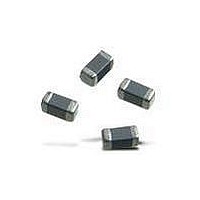
Product
Chip Ferrite Beads
Impedance
75 Ohms
Tolerance
25 %
Maximum Dc Current
300 mAmps
Maximum Dc Resistance
0.7 Ohms
Operating Temperature Range
- 55 C to + 125 C
Package / Case
0603 (1608 metric)
Termination Style
SMD/SMT
Dc Resistance Max
0.7ohm
Dc Current Rating
300mA
Ferrite Mounting
SMD
Ferrite Case Style
0603
Inductor Case Style
0603
No. Of Pins
2
Core Material
Ferrite
Resistance
0.7ohm
Rohs Compliant
Yes
Operating Temperature Min
-55°C
Operating Temperature Max
+125°C
Lead Free Status / RoHS Status
Lead free / RoHS Compliant
Available stocks
Company
Part Number
Manufacturer
Quantity
Price
Company:

Part Number:
BLM18BA750SN1D
Manufacturer:
MURATA
Quantity:
12 000


!Note
• This PDF catalog is downloaded from the website of Murata Manufacturing co., ltd. Therefore, it’s specifications are subject to change or our products in it may be discontinued without advance notice. Please check with our
• This PDF catalog has only typical specifications because there is no space for detailed specifications. Therefore, please approve our product specifications or transact the approval sheet for product specifications before ordering.
sales representatives or product engineers before ordering.
!Note
10. Expressing EMI Suppression Filter Effects
EMI Suppression Filter effects are expressed in terms of
the insertion loss measured in the circuit, normally
specified in MIL-STD 220A. As shown in the 50
impedance circuit in the Figure at right, insertion loss is
represented by the logarithmic ratio of the circuit output
voltage with and without a filter in the circuit, which is
multiplied by 20 and expressed in dB.
Therefore, an insertion loss of 20dB indicates an output
voltage ratio (B/C) of 1/10, and an insertion loss of 40dB
indicates an output voltage ratio (B/C) of 1/100.
Continued from the preceding page.
• Please read rating and !CAUTION (for storage, operating, rating, soldering, mounting and handling) in this catalog to prevent smoking and/or burning, etc.
• This catalog has only typical specifications because there is no space for detailed specifications. Therefore, please approve our product specifications or transact the approval sheet for product specifications before ordering.
Principles of Noise Suppression by DC EMIFILr
Measuring Circuit of Insertion Loss
(a)
(b)
Measuring Circuit of Insertion Loss
Insertion Loss = 20 log B (dB)
A(V)
A(V)
50
50
Suppression
Filter
EMI
C
B(V)
C(V)
50
50
211
C31E.pdf
08.9.1
Related parts for BLM18BA750SN1D
Image
Part Number
Description
Manufacturer
Datasheet
Request
R

Part Number:
Description:
Murata Microblower 20x20 DCDC Driver Board - Samples Only
Manufacturer:
Murata
Part Number:
Description:
357-036-542-201 CARDEDGE 36POS DL .156 BLK LOPRO
Manufacturer:
Murata
Datasheet:
Part Number:
Description:
Manufacturer:
Murata
Datasheet:
Part Number:
Description:
Manufacturer:
Murata
Datasheet:
Part Number:
Description:
Manufacturer:
Murata
Datasheet:
Part Number:
Description:
Manufacturer:
Murata
Datasheet:
Part Number:
Description:
Manufacturer:
Murata
Datasheet:
Part Number:
Description:
Manufacturer:
Murata
Datasheet:
Part Number:
Description:
Manufacturer:
Murata
Datasheet:
Part Number:
Description:
BLM21BD751SN1On-Board Type (DC) EMI Suppression Filters
Manufacturer:
Murata
Datasheet:
Part Number:
Description:
BLM15AG100SN1On-Board Type (DC) EMI Suppression Filters
Manufacturer:
Murata
Datasheet:
Part Number:
Description:
NFE31PT222Z1E9On-Board Type (DC) EMI Suppression Filters
Manufacturer:
Murata
Datasheet:
Part Number:
Description:
Chip Coil
Manufacturer:
Murata
Datasheet:
Part Number:
Description:
Chip Coil
Manufacturer:
Murata
Datasheet: