UTS10DCG Souriau Connection Technology, UTS10DCG Datasheet - Page 30
UTS10DCG
Manufacturer Part Number
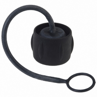
UTS10DCG
Description
CONN RCPT SEALING CAP SIZE 10
Manufacturer
Souriau Connection Technology
Series
Trim Trio® UTSr
Specifications of UTS10DCG
Accessory Type
Cap (Cover), Sealing
Shell Size - Insert
10
Features
Metal Chain
Color
Black
Mil Type
MIL-DTL-26482 I
Product Type
Dustcaps
Shell Style
Receptacle
Shell Size
10
Mounting Style
Through Hole
Termination Style
Screw
Mounting Angle
Straight
Connector Shell Size
10
Connector Body Material
Plastic
Body Material
Plastic
Rohs Compliant
Yes
Lead Free Status / RoHS Status
Lead free / RoHS Compliant
For Use With/related Products
Trim Trio® UTS Receptacle
For Use With
SOU1525 - CONN RCPT JAM NUT 6POS W/SCKTSOU1524 - CONN RCPT JAM NUT 6POS W/PINSOU1290 - CONN RCPT 6X1.0 MALE JAM NUTSOU1289 - CONN RCPT 4X1.6 MALE JAM NUTSOU1288 - CONN RCPT 3X1.6 MALE JAM NUTSOU1281 - CONN RCPT 6X1.0 FEMALE JAM NUTSOU1280 - CONN RCPT 4X1.6 FEMALE JAM NUTSOU1279 - CONN RCPT 3X1.6 FEMALE JAM NUT
Lead Free Status / Rohs Status
Lead free / RoHS Compliant
Other names
SOU1315


<<
UTS Series
Special case with the tool RX2025GE1:
A - When setting up in the cell, keep firmly
the tool
by the hexagonal metallic part and insert tool
in cavity.
B - Push the tool by the handle to extract the
contact.
A
Contact size
Quadrax
Square flange receptacle
#20
#1 6
#1 2
#8
UTS0
A
5106.021.09.24
5106.021.09.36
VGE1-0324A
RX2025GE1
RX20D44
Extractor
B
C
Extraction tools instruction for size 1 6
D
5106.021.09.24
Jam nut receptacle
UTS7
RX2025GE1
Extraction tools
Panel cut out
58
E
5106.021.09.36
Shell
size
1 0
1 2
1 4
1 8
8
A
18.3
20.6
23.0
1 5.1
27.0
±0.25
Ø B
Extraction:
Place the tool into the cavity from
front face of the connector, push
on the handle, then remove the
contact..
3.2
±0.1
mounting
Front
18.2
21.4
1 2.5
1 5.1
27.8
RX20D44
Ø C
±0.1
mounting
Rear
22.2
25.5
31.8
1 4.5
1 7.8
Ø D
22.5
25.7
1 4.6
1 7.7
VGE1-0324A
32
±0.2
1 3.75
E
16.5
21.2
24.3
30.6
±0.2
UTS Series
Rated current & working voltage
The current carrying capacity of a connector is limited by the thermal properties of materials used in it's construction. The amount of current
that can be handled depends on the size of cable used, the ambient temperature and the heat that is generated inside the connector. Part 3
of the IEC 6051 2 standard determines through a derating curve, the maximum current permissible, which varies from one layout to another
(Fig.1 & Fig.2). Wire size plays an important role as well, since they help to dissipate heat and avoid overheating (Fig.1 & Fig.3).
Please note that the curve should be adjusted when dealing with potential hot spots, which can occur as a result of unequal loading of current
across a number of contacts. As a general rule, it is best to avoid locating power handling contacts in the middle of the connector; try to locate
them towards the edge where heat can be dissipated more effectively. Eventually you should find a level which represents the permissible
operating range:
The rated current is defined as uninterrupted continuous current that a connector can take when all contacts are energized simultaneously
without exceeding the maximum limit of temperature. The earth contact is never loaded.
30
28
25
23
20
18
10
35
33
30
28
25
23
20
18
10
1 5
1 3
1 5
1 3
8
5
3
0
8
5
3
0
0
0
20
20
Fig.3: UTS 1 2-4 – 2.5mm² wires
Fig.1: UTS 1 2-4 – 1 .5mm² wires
Ambient Operating Temperature (°C)
Ambient Operating Temperature (°C)
40
40
60
60
80
80
Current carrying capacity
100
100
1 20
1 20
59
30
28
25
23
20
18
10
1 5
1 3
8
5
3
0
0
20
Fig.2: UTS 1 2-8 – 1 .5mm² wires
Ambient Operating Temperature (°C)
Current use
Limited use
Not recommended use
40
60
80
100
1 20
>>
Related parts for UTS10DCG
Image
Part Number
Description
Manufacturer
Datasheet
Request
R

Part Number:
Description:
CONN SEALING FOR WALL RCPT #22
Manufacturer:
Souriau Connection Technology
Part Number:
Description:
CONN SEALING FOR WALL RCPT #14
Manufacturer:
Souriau Connection Technology
Datasheet:

Part Number:
Description:
CONN RCPT SEALING CAP SIZE 14
Manufacturer:
Souriau Connection Technology
Datasheet:

Part Number:
Description:
CONN STRAIN RELIEF 12POS
Manufacturer:
Souriau Connection Technology
Datasheet:

Part Number:
Description:
CONN PLUG SEALING CAP SIZE 12
Manufacturer:
Souriau Connection Technology
Datasheet:

Part Number:
Description:
D38999 Series 3
Manufacturer:
Souriau Connection Technology
Datasheet: