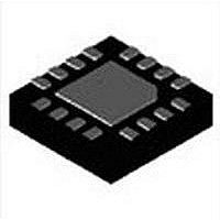
MAX5974AETE+ Maxim Integrated Products, MAX5974AETE+ Datasheet

MAX5974AETE+
Specifications of MAX5974AETE+
Related parts for MAX5974AETE+
MAX5974AETE+ Summary of contents
Page 1
... The programmable frequency dither- ing feature provides low-EMI, spread-spectrum operation. The MAX5974_ are available in 16-pin TQFN-EP pack- ages and are rated for operation over the -40°C to +85°C temperature range. PART TOP MARK MAX5974AETE+ +AHY MAX5974BETE+ +AHZ MAX5974CETE+ +AIA MAX5974DETE+ +AIB Note: All devices are specified over the -40° ...
Page 2
Active-Clamped, Spread-Spectrum, Current-Mode PWM Controllers ABSOLUTE MAXIMUM RATINGS IN to GND ..............................................................-0.3V to +26V EN, NDRV, AUXDRV to GND .....................-0. RT, DT, FFB, COMP, SS, DCLMP, DITHER/SYNC to GND .................................................................-0. GND (MAX5974A/MAX5974B only) ..................-6V ...
Page 3
Active-Clamped, Spread-Spectrum, ELECTRICAL CHARACTERISTICS (continued 12V (for MAX5974A/MAX5974C, bring +2V, NDRV = AUXDRV = SS = COMP = unconnected, R GND EN unless otherwise noted. Typical values are at T PARAMETER SYMBOL ...
Page 4
Active-Clamped, Spread-Spectrum, Current-Mode PWM Controllers ELECTRICAL CHARACTERISTICS (continued 12V (for MAX5974A/MAX5974C, bring +2V, NDRV = AUXDRV = SS = COMP = unconnected, R GND EN unless otherwise noted. Typical values are at ...
Page 5
Active-Clamped, Spread-Spectrum, ELECTRICAL CHARACTERISTICS (continued 12V (for MAX5974A/MAX5974C, bring +2V, NDRV = AUXDRV = SS = COMP = unconnected, R GND EN unless otherwise noted. Typical values are at T PARAMETER SYMBOL ...
Page 6
Active-Clamped, Spread-Spectrum, Current-Mode PWM Controllers (V = 12V (for MAX5974A/MAX5974C, bring 2V, NDRV = AUXDRV = SS = COMP = unconnected, R GND EN IN UVLO WAKE-UP LEVEL vs. TEMPERATURE 20.1 MAX5974A/MAX5974C 20.0 19.9 ...
Page 7
Active-Clamped, Spread-Spectrum 12V (for MAX5974A/MAX5974C, bring 2V, NDRV = AUXDRV = SS = COMP = unconnected, R GND EN SOFT-START CHARGING CURRENT vs. TEMPERATURE 10.06 10.05 10.04 10.03 10.02 10.01 10.00 9.99 ...
Page 8
Active-Clamped, Spread-Spectrum, Current-Mode PWM Controllers (V = 12V (for MAX5974A/MAX5974C, bring 2V, NDRV = AUXDRV = SS = COMP = unconnected, R GND EN DEAD TIME vs. R VALUE DT 400 350 300 250 ...
Page 9
Active-Clamped, Spread-Spectrum 12V (for MAX5974A/MAX5974C, bring 2V, NDRV = AUXDRV = SS = COMP = unconnected, R GND EN TRANSCONDUCTANCE vs. TEMPERATURE 3.0 2.9 MAX5974C/MAX5974D 2.8 2.7 2.6 2.5 2.4 MAX5974A/MAX5974B 2.3 ...
Page 10
Active-Clamped, Spread-Spectrum, Current-Mode PWM Controllers (V = 12V (for MAX5974A/MAX5974C, bring 2V, NDRV = AUXDRV = SS = COMP = unconnected, R GND EN V RAMP RESPONSE DCLMP MAX5974A/B/C/D toc35 V DCLMP 2V/div V ...
Page 11
Active-Clamped, Spread-Spectrum, TOP VIEW PIN NAME Dead-Time Programming Resistor Connection. Connect resistor desired dead time between the NDRV and AUXDRV signals. See the Dead Time section to calcu- late the resistor value for a particular dead time. ...
Page 12
Active-Clamped, Spread-Spectrum, Current-Mode PWM Controllers PIN NAME 6 FB Transconductance Amplifier Inverting Input 7 GND Signal Ground Current Sense with Slope Compensation Input. A resistor connected from CSSC to CS programs the 8 CSSC amount of slope compensation. See the ...
Page 13
Active-Clamped, Spread-Spectrum, Current-Mode PWM Controllers Block Diagrams 13 ...
Page 14
Active-Clamped, Spread-Spectrum, Current-Mode PWM Controllers 14 Block Diagrams (continued) ...
Page 15
Active-Clamped, Spread-Spectrum, Detailed Description The MAX5974A/MAX5974B/MAX5974C/MAX5974D are optimized for controlling a 25W to 50W active-clamped, self-driven synchronous rectification forward converter in continuous-conduction mode. The main switch gate driver (NDRV) and the active-clamped switch driver (AUXDRV) are sized to optimize efficiency ...
Page 16
Active-Clamped, Spread-Spectrum, Current-Mode PWM Controllers EN1 DIGITAL CONTROL R N EN2 Figure 1. Programmable UVLO for the Power Source DIGITAL EN CONTROL N Figure 2. External Control ...
Page 17
Active-Clamped, Spread-Spectrum, startup to provide a slow and smooth increase of the duty cycle to its steady-state value. Calculate the value follows × t SS- where I (10FA typ) is the ...
Page 18
Active-Clamped, Spread-Spectrum, Current-Mode PWM Controllers Oscillator/Switching Frequency The ICs’ switching frequency is programmable between 100kHz and 600kHz with a resistor R between RT and GND. Use the following formula to determine the appropriate value of R erate the desired output-switching ...
Page 19
Active-Clamped, Spread-Spectrum, Frequency Foldback for High-Efficiency Light-Load Operation The frequency foldback threshold can be programmed from 0 to 20% of the full load current using a resistor from FFB to GND. When V falls below V , the device folds ...
Page 20
Active-Clamped, Spread-Spectrum, Current-Mode PWM Controllers Typically, f should be set close to 1kHz. The resistor TRI R connected from DITHER/SYNC to RT deter- DITHER mines the amount of dither as follows × %DITHER 3 R DITHER where ...
Page 21
Active-Clamped, Spread-Spectrum, Active Clamp Circuit Traditional clamp circuits prevent transformer saturation by channeling the magnetizing current (I former onto a dissipative RC network. To improve effi- ciency, the active clamp circuit recycles I magnetizing inductance and clamp capacitor ...
Page 22
Active-Clamped, Spread-Spectrum, Current-Mode PWM Controllers During on-time, the coupled output is − (V × COUPLED- where V is the input supply voltage. S Care must be taken to ensure that the voltage at ...
Page 23
Active-Clamped, Spread-Spectrum 36V TO 57V C BULK 33µ 100kI C IN 1µF 25V R DCLMP1 IN 30. DCLMP2 750 I 1% DCLMP C SS 0.1µF SS MAX5974C R DT MAX5974D 16.9k I ...
Page 24
Active-Clamped, Spread-Spectrum, Current-Mode PWM Controllers V S 36V TO 57V C BULK 33µ 63V 100kI R DCLMP1 30. DCLMP2 750 I 1% DCLMP C SS 0.1µF SS MAX5974A R DT MAX5974B 16.9k I ...
Page 25
Active-Clamped, Spread-Spectrum BULK DCLMP1 EN R DCLMP2 DCLMP MAX5974C R MAX5974D DITHER C DITHER DITHER/ SYNC FFB FFB FB COMP R z GND ...
Page 26
... Maxim cannot assume responsibility for use of any circuitry other than circuitry entirely embodied in a Maxim product. No circuit patent licenses are implied. Maxim reserves the right to change the circuitry and specifications without notice at any time. Maxim Integrated Products, 120 San Gabriel Drive, Sunnyvale, CA 94086 408-737-7600 26 2010 Maxim Integrated Products © ...


