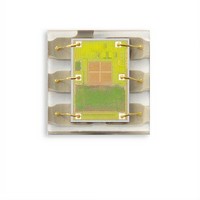
TSL27713FN TAOS, TSL27713FN Datasheet - Page 28

TSL27713FN
Manufacturer Part Number
TSL27713FN
Description
Light to Digital Converters Light to Digital w/Proximity
Manufacturer
TAOS
Datasheet
1.TSL27713FN.pdf
(36 pages)
Specifications of TSL27713FN
Data Bus Width
16 bit
Peak Wavelength
640 nm, 850 nm
Maximum Operating Frequency
795 KHz
Operating Supply Voltage
2.4 V to 3.6 V
Operating Current
175 uA
Maximum Operating Temperature
+ 70 C
Minimum Operating Temperature
- 30 C
Interface Type
I2C
Maximum Fall Time
300 ns
Maximum Rise Time
300 ns
Mounting Style
SMD/SMT
Resolution
16 bit
Package / Case
DFN-6
Lead Free Status / RoHS Status
Lead free / RoHS Compliant
Available stocks
Company
Part Number
Manufacturer
Quantity
Price
Company:
Part Number:
TSL27713FN
Manufacturer:
DETRON
Quantity:
380
TSL2771
LIGHT-TO-DIGITAL CONVERTER
with PROXIMITY SENSING
TAOS100A − FEBRUARY 2010
Status Register (0x13)
ADC Channel Data Registers (0x14 − 0x17)
Proximity Data Register (0x18 − 0x19h)
28
Copyright E 2010, TAOS Inc.
STATUS
Reserved
Reserved
AVALID
FIELD
PINT
AINT
The Status Register provides the internal status of the device. This register is read only.
ALS clear and IR data are stored as two 16-bit values. To ensure the data is read correctly, a two-byte read I
transaction should be used with auto increment protocol bits set in the command register. With this operation,
when the lower byte register is read, the upper eight bits are stored in a shadow register, which is read by a
subsequent read to the upper byte. The upper register will read the correct value even if additional ADC
integration cycles end between the reading of the lower and upper registers.
Proximity data is stored as a 16-bit value. To ensure the data is read correctly, a two-byte read I
should be utilized with auto increment protocol bits set in the command register. With this operation, when the
lower byte register is read, the upper eight bits are stored into a shadow register, which is read by a subsequent
read to the upper byte. The upper register will read the correct value even if the next ADC cycle ends between
the reading of the lower and upper registers.
BIT
7:6
3:1
7
5
4
0
Reserved
REGISTER
REGISTER
IRDATAH
IRDATAL
CDATAH
PDATAH
CDATAL
PDATAL
Reserved.
Proximity Interrupt. Indicates that the device is asserting a proximity interrupt.
ALS Interrupt. Indicates that the device is asserting an ALS interrupt.
Reserved.
ALS Valid. Indicates that the ALS clear / IR channels have completed an integration cycle.
6
ADDRESS
ADDRESS
Table 15. ADC Channel Data Registers
0x14
0x15
0x16
0x17
0x18
0x19
PINT
Resv
5
r
Table 16.
Table 14. Status Register
www.taosinc.com
AINT
BITS
BITS
7:0
7:0
7:0
7:0
7:0
7:0
4
PDATA Register
ALS clear data low byte
ALS clear data high byte
ALS IR data low byte
ALS IR data high byte
Proximity data low byte
Proximity data high byte
3
DESCRIPTION
Reserved
s
DESCRIPTION
DESCRIPTION
2
r
1
The LUMENOLOGY r Company
AVALID
0
2
C transaction
Address
0x13
2
C


