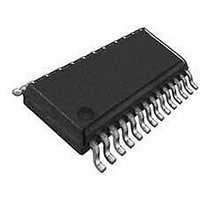
WM8741GEDS/V Wolfson Microelectronics, WM8741GEDS/V Datasheet - Page 19

WM8741GEDS/V
Manufacturer Part Number
WM8741GEDS/V
Description
Audio D/A Converter ICs Stereo DAC, High End
Manufacturer
Wolfson Microelectronics
Datasheet
1.WM8741GEDSV.pdf
(64 pages)
Specifications of WM8741GEDS/V
Mounting Style
SMD/SMT
Package / Case
SSOP-28
Lead Free Status / RoHS Status
Lead free / RoHS Compliant
Available stocks
Company
Part Number
Manufacturer
Quantity
Price
Company:
Part Number:
WM8741GEDS/V
Manufacturer:
Wolfson Microelectronics
Quantity:
1 881
Production Data
SOFTWARE CONTROL INTERFACE
w
The software control interface may be operated using a 2-wire or 3-wire (SPI-compatible) serial
interface. When operating under serial control, hardware configuration pins are ignored.
Note: DIFFHW will override all other pins, forcing the device into hardware control mode and
differential mono mode.
3-WIRE (SPI COMPATIBLE) SERIAL CONTROL MODE
Every rising edge of SCLK clocks in one bit of data on SDIN. A rising edge on CSB latches a
complete control word consisting of 16 bits. The 3-wire interface protocol is shown in Figure 9.
Figure 9 3-wire Serial Interface Protocol
Notes:
1.
2.
3.
3-WIRE CONTROL INTERFACE DAISY CHAINING
In daisy chaining mode, SDOUT (pin 25) outputs control data sampled on SDIN with a delay of 16
SCLK cycles. This data signal can be used to control another WM8741 in a daisy chain circuit as
shown in Figure 10.
Figure 10 Control Interface Daisy Chaining Setup
To configure devices into daisy chain mode the CSB signal should be driven low while there is a
register write to set register bit SDOUT=1. CSB should then be driven high, this sets the first device
in daisy chain mode. CSB should then be driven low again while register bit SDOUT is set high.
Setting CSB high again will cause the first register write to be output to the second device from the
SDOUT pin, this sets the second device into daisy chain mode. This method must be repeated for
the number of devices in the chain until they are all set into daisy chain mode. Figure 11 shows the
protocol for configuring the first two devices in the daisy chain.
A[6:0] are Control Address Bits
D[7:0] are Control Data Bits
D[8] is always set to zero
DAC #1
DAC #2
DAC #3
PD, Rev 4.2, October 2009
WM8741
19


