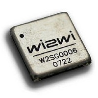
W2SG0006-006 Wi2Wi, W2SG0006-006 Datasheet - Page 5

W2SG0006-006
Manufacturer Part Number
W2SG0006-006
Description
GPS Modules & Development Tools 9600bps/NMEAOutput- GGAGSARMCGSV-1Hz
Manufacturer
Wi2Wi
Type
GPS Moduler
Datasheet
1.W2SG0006-006.pdf
(20 pages)
Specifications of W2SG0006-006
Operating Voltage
3.3 VDC
Operating Current
47 mA
Frequency Range
1.57542 GHz
Interface Type
UART
Operating Temperature Range
- 30 C to + 85 C
For Use With/related Products
W2SG0006-DEV
Lead Free Status / RoHS Status
Lead free / RoHS Compliant
2.1
The functional pin definition for the W2SG0006 is presented below in
Pin Definition
Pin
10
11
12
13
14
15
16
17
18
19
20
21
22
23
24
25
26
27
28
1
2
3
4
5
6
7
8
9
TIMESYNC (YCLK)
FLASH_ENABLE
BACKUP_CELL
GPS_ENABLE
VCC_LNA
VCC_ANT
RTC_OUT
VDD_3V3
VDD_3V3
ANT_IN
GPIO13
GPIO14
GPIO9
GPIO4
GPIO1
Signal
ECLK
GND
GND
GND
GND
GND
GND
RXA
GND
GND
TXA
RXB
TXB
Type
PWR
PWR
PWR
PWR
PWR
PWR
PWR
PWR
PWR
I/O
I/O
I/O
I/O
I/O
O
O
O
O
I
I
I
I
I
I
I
I
I
I
Copyright © 2009 Wi2Wi, Inc.
Table 1: Pin Definition
Ground
Ground
General Purpose I/O; Default configuration is for generating 1PPS
Time Mark Output; Leave unconnected if it is not used
3.3V Power supply
GPS Enable; Connect to ground if there is no external control
Flash programming; Pull high to 3.3V DC for flash mode and pull
low for normal operation
Ground
Generel Purpose I/O; Leave unconnected if it is not used
General Purpose I/O; Leave unconnected if it is not used
Ground
General Purpose I/O; Leave unconnected if it is not used
General Purpose I/O; Leave unconnected if it is not used
Ground
Connect to the backup battery as shown in Figure 4; Leave
unconnected if it is not used
Ground
UART Input Port for Channel A; Maximum voltage at this port
should be 3.0V.
UART Output Port for Channel A; Maximum output voltage at
this port is 3.0V.
Ground
3.3V power supply
2.85V DC Regulated Output
Active antenna bias input; Connect to 3.3V DC is using active
antenna; Leave unconnected if using passive antenna
Antenna RF Input (50 ohm impedance)
Ground
It is the output of the crystal oscillator located in the RF section of
the chip; It is for minotoring purposes only and should be left
unconnected if it is not used.
UART Input Port for Channel B; Maximum voltage at this port
should be 3.0V.
UART Output Port for Channel B; Maximum output voltage at
this port is 3.0V.
External CMOS clock input only for AGPS applications under
SiRFLoc Client software;Leave unconnected if it is not used
Timesync(Yclk) is an auxiliary clock input that supports alternate
oscillator calibration system; It is used to for SiRFLoc Client time
aiding information; Leave unconnected if it is not used
Table 1
Wi2Wi, Inc. Doc No. A06-PDT-DOC Rev.1.64
Description
.
Datasheet, GPS Module– W2SG0006
Page 5 of 20
Dated: July 10, 2009


