SAM7-P256 Olimex Ltd., SAM7-P256 Datasheet
SAM7-P256
Specifications of SAM7-P256
Available stocks


Related parts for SAM7-P256


SAM7-P256 Summary of contents
Page 1
... SAM7-P256 development board All boards produced by Olimex are ROHS compliant Copyright(c) 2010, OLIMEX Ltd, All rights reserved Users Manual Rev. F, August 2008 Page 1 ...
Page 2
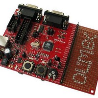
... INTRODUCTION: Atmel’s AT91SAM7S256 is a member of a series of low pincount Flash mi- crocontrollers based on the 32-bit ARM RISC processor. It features a 256 Kbyte high-speed Flash and a 64 Kbyte SRAM, a large set of peripherals, including a USB 2.0 device, and a complete set of system functions minimizing the number of ex- ternal components ...
Page 3
... ELECTROSTATIC WARNING: The SAM7-P256 board is shipped in protective anti-static packaging. The board must not be subject to high electrostatic potentials. General practice for working with static sensitive devices should be applied when working with this board. BOARD USE REQUIREMENTS: Cables: The cable you will need depends on the programmer/debugger you use. If you use ARM-JTAG-EW, you will need USB A-B cable ...
Page 4
Kbytes Memory Controller (MC) Embedded Flash Controller, Abort Status and Misalignment Detection Reset Controller (RSTC) Based on Power-on Reset and Low-power Factory-calibrated Brown-out Detector Provides External Reset Signal Shaping and Reset Source Status Clock Generator (CKGR) Low-power RC Oscillator, ...
Page 5
Eleven Peripheral DMA Controller (PDC) Channels One USB 2.0 Full Speed (12 Mbits per Second) Device Port On-chip Transceiver, 328-byte Configurable Integrated FIFOs One Synchronous Serial Controller (SSC) Independent Clock and Frame Sync Signals for Each Receiver and Transmitter I ...
Page 6
VDDCORE Core Power Supply with Brown-out Detector Fully Static Operation MHz at 1.65V and 85ーC Worst Case Condition Page 6 ...
Page 7
BLOCK DIAGRAM: Page 7 ...
Page 8
MEMORY MAP: Page 8 ...
Page 9
SCHEMATIC USB Page 9 ...
Page 10
BOARD LAYOUT: Page 10 ...
Page 11
... POWER SUPPLY CIRCUIT: SAM7-P256 is typically power supplied with 6 VDC. The programmed board power consumption is about 30 mA. RESET CIRCUIT: SAM7-P256 reset circuit includes U5 (MCP130T), R8 (10k), pin 15 of JTAG connector, pin 39 (NRST) of AT91SAM7S256 and RESET button. CLOCK CIRCUIT: Quartz crystal Q1 18.432 MHz is connected to AT91SAM7S256 pin 61 (XOUT) and pin 62 (XIN) ...
Page 12
... User button with name B1 connected to AT91SAM7S256 pin 13 (PA19/RK/FIQ/AD2). User button with name B2 connected to AT91SAM7S256 pin 16 (PA20/RF/IRQ0/AD3). User button with name RESET connected to AT91SAM7S256 pin 39 (NRST). Trimpot with name AN_TR connected to AT91SAM7S256 pin 3 (AD4). Thermistor with name TH1 connected to AT91SAM7S256 pin 4 (AD5). Page 12 TM software ...
Page 13
EXTERNAL CONNECTORS DESCRIPTION: RS232_0/D: Pin # RS232_1: Pin # Signal Name NC TX0OUT RX0IN NC GND Signal Name ...
Page 14
... The JTAG connector allows the software debugger to talk via a JTAG (Joint Test Action Group) port directly to the core. Instructions may be inserted and executed by the core thus allowing AT91SAM7S256 memory to be programmed with code and executed step by step by the host software. For more details refer to IEEE Standard 1149.1 - 1990 Standard Test Access Port and Boundary Scan Architecture and AT91SAM7S256 datasheets and users manual ...
Page 15
Pin # 1 3.3V 3 TRST 5 TDI 7 TMS 9 TCK 11 RTCK 13 TDO 15 RST USB Pin # Signal Name 1 +5V_USB 2 DDM 3 DDP 4 GND SD/MMC Signal Name Pin # ...
Page 16
Pin # Signal Name 1 NPCS0 3 GND (VSS1) 5 SPCK 7 MISO 9 Via R31 (47k) to 3.3V 11 Via R19 (2k) to GND Via R24 (2k) to GND Pin # Signal Name 2 MOSI 4 ...
Page 17
EXTENSION PORT Page 17 ...
Page 18
MECHANICAL DIMENSIONS: Page 18 ...
Page 19
... AVAILABLE DEMO SOFTWARE: SAM7-P256 blinking LED project and binary code for SAM-BA load SAM7-P256 sample mouse driver project UART routines project SD/MMC read/write routines project button read, temperature measurement project MOD-SMB380 read demo code for EW-ARM 4.11 with SAM7-P64/256 board ...
Page 20
... ORDER CODE: SAM7-P256 - How to order? You can order to us directly or by any of our distributors. Check our web www.olimex.com/dev Revision history: Revision F, August 2008 assembled and tested board for more info. Page 20 ...
Page 21
... However all warranties implied or expressed including but not limited to implied warranties of merchantability or fitness for purpose are excluded. This document is intended only to assist the reader in the use of the product. OLIMEX Ltd. shall not be liable for any loss or damage arising from the use of any information in this document or any error or omission in such information or any incorrect use of the product ...