STM32-H103 Olimex Ltd., STM32-H103 Datasheet - Page 13
STM32-H103
Manufacturer Part Number
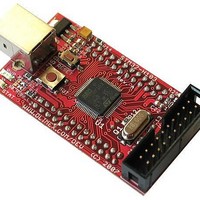
STM32-H103
Description
MCU, MPU & DSP Development Tools HDR BRD FOR STM32F103RBT6
Manufacturer
Olimex Ltd.
Datasheet
1.STM32-H103.pdf
(17 pages)
Specifications of STM32-H103
Processor To Be Evaluated
STM32F103RBT6
Data Bus Width
32 bit
Interface Type
USB, CAN, I2C, JTAG, SPI, UART
Dimensions
61 mm x 34 mm
Operating Supply Voltage
3.3 V
Core Architecture
ARM
Cpu Core
ARM Cortex M3
Lead Free Status / RoHS Status
Lead free / RoHS Compliant
Available stocks
Company
Part Number
Manufacturer
Quantity
Price
Company:

Part Number:
STM32-H103
Manufacturer:
Olimex Ltd.
Quantity:
135


CAN:
USB:
ADC:
The STM32F103RBT6 CAN is compliant with specifications 2.0A and B
(active) with a bit rate up to 1 Mbit/s. It can receive and transmit standard
frames with 11-bit identifiers as well as extended frames with 29-bit
identifiers. It has three transmit mailboxes, two receive FIFOs with 3 stages
and 14 scalable filter banks.
The CAN and USB share same pins PA11/EXT1-1 and PA12/EXT1-3, so
you can’t use both CAN and USB on same time.
The STM32F103RBT6 embeds a USB device peripheral compatible with the
USB Full-speed 12 Mbs. The USB interface implements a full speed (12
Mbit/s) function interface. It has software configurable endpoint setting
and suspend/resume support. The dedicated 48 MHz clock source is
generated from the internal main PLL.
The CAN and USB share same pins PA11/EXT1-1 and PA12/EXT1-3, so
you can’t use both CAN and USB on same time.
STM32F103RBT6 have two 12-bit Analog to Digital Converters which share
up to 16 external channels, performing conversions in singleshot or scan
modes. In scan mode, automatic conversion is performed on a selected
group of analog inputs.
Additional logic functions embedded in the ADC interface allow:
- Simultaneous sample and hold
- Interleaved sample and hold
- Single shunt
The ADC can be served by the DMA controller.
An analog watchdog feature allows very precise monitoring of the converted
voltage of one, some or all selected channels. An interrupt is generated
when the converted voltage is outside the programmed thresholds. The
events generated by the standard timers (TIMx) and the Advanced Control
timer (TIM1) can be internally connected to the ADC start trigger, injection
trigger, and DMA trigger respectively, to allow the application to
synchronize A/D conversion and timers.
Related parts for STM32-H103
Image
Part Number
Description
Manufacturer
Datasheet
Request
R

Part Number:
Description:
MCU, MPU & DSP Development Tools HDR BRD FOR STM32F103RBT6
Manufacturer:
Olimex Ltd.
Datasheet:

Part Number:
Description:
MCU, MPU & DSP Development Tools STARTERKIT BRD FOR STM32F103RBT6
Manufacturer:
Olimex Ltd.
Datasheet:

Part Number:
Description:
Development Boards & Kits - ARM PROTOTYPE BRD STM32F407
Manufacturer:
Olimex Ltd.
Part Number:
Description:
Development Boards & Kits - ARM PROTOTYPE BRD STM32F207
Manufacturer:
Olimex Ltd.
Part Number:
Description:
Microcontroller Modules & Accessories PROTOTYPE BOARD FOR STM32F107VCT6
Manufacturer:
Olimex Ltd.
Part Number:
Description:
MCU, MPU & DSP Development Tools HEADER BOARD FOR STM32F107
Manufacturer:
Olimex Ltd.
Part Number:
Description:
Development Boards & Kits - ARM DEVELOPMENT BOARD STM32F407ZGT6
Manufacturer:
Olimex Ltd.
Part Number:
Description:
Development Boards & Kits - ARM DEVELOPMENT BOARD STM32F407ZGT6
Manufacturer:
Olimex Ltd.
Part Number:
Description:
Development Boards & Kits - ARM PROTOTYPE BRD STM32L152VBT6
Manufacturer:
Olimex Ltd.
Part Number:
Description:
Development Boards & Kits - ARM HDR BOARD FOR STM32L152VBT6
Manufacturer:
Olimex Ltd.

Part Number:
Description:
Microcontroller & Microprocessor Development Tools TCP-IP DEV BRD PIC32MX460F512
Manufacturer:
Olimex Ltd.
Datasheet:

Part Number:
Description:
Microcontroller & Microprocessor Development Tools PROTOTYPE BOARD TMS320F28027
Manufacturer:
Olimex Ltd.
Datasheet:

Part Number:
Description:
Microcontroller & Microprocessor Development Tools HDR BRD FOR LPC3131
Manufacturer:
Olimex Ltd.
Datasheet:

Part Number:
Description:
Microcontroller & Microprocessor Development Tools MP3 PLYR MOD WITH VS1002
Manufacturer:
Olimex Ltd.
Datasheet:
Part Number:
Description:
Microcontroller & Microprocessor Development Tools MP3 PLYR MOD BAT WITH VS1002
Manufacturer:
Olimex Ltd.
Datasheet: