PIC-USB-STK Olimex Ltd., PIC-USB-STK Datasheet - Page 9
PIC-USB-STK
Manufacturer Part Number
PIC-USB-STK
Description
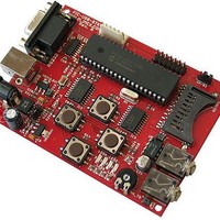
MCU, MPU & DSP Development Tools STARTERKIT BRD FOR PIC18F4550 W/USB
Manufacturer
Olimex Ltd.
Datasheet
1.PIC-USB-STK.pdf
(17 pages)
Specifications of PIC-USB-STK
Processor To Be Evaluated
PIC18F4550
Interface Type
RS-232, USB
Dimensions
104 mm x 76 mm
Operating Supply Voltage
5 V
Silicon Manufacturer
Microchip
Core Architecture
PIC
Core Sub-architecture
PIC18
Silicon Core Number
PIC18F
Silicon Family Name
PIC18F4xxx
Kit Contents
Board
Rohs Compliant
Yes
Lead Free Status / RoHS Status
Lead free / RoHS Compliant
Other names
1701542 25R4929


JUMPER DESCRIPTION:
SMD jumper description
PTH jumper description:
B4_E
EXT/USB
CP/B2
B3_E
The B4_E jumper connects Button 4 with PB6/PGC pin of
PIC18F4550. In debug mode please do not press Button 4 as
this will corrupt ProgramClock PB6 line and the result will be
not predictable
Default state - closed
PIC18F4550. In debug mode please do not press Button 3 as
this will corrupt ProgramData PB7 and the result will be not
predictable.
The B3_E jumper connects Button 3 with PB7/PGD pin of
Default state - closed
The EXTernal/USB jumper defines the power source which
supply the board.
EXT position – The board is supplied from PWR_JACK(6VAC or
9VDC).
USB position – The board is supplied from USB type B
connector.
Default state
CP position – Card Present pin of SD/MMC socket is
connected to PB4(pin37)
B2 position – Button 2 is connected to PB4(pin37).
Button 2 is used for boot mode entry. If CP/B2 jumper is in B2
state and B2 is pressed at power up, the board enters in boot
mode.
Default state
i.e. Button 4 is enabled
EXT
i.e. Button 3 is enabled
B2
Related parts for PIC-USB-STK
Image
Part Number
Description
Manufacturer
Datasheet
Request
R

Part Number:
Description:
MCU, MPU & DSP Development Tools PROTOTYPE BRD FOR PIC18F4550 W/USB
Manufacturer:
Olimex Ltd.
Datasheet:

Part Number:
Description:
Microcontroller Modules & Accessories USB ADAPTER FOR PIC-MCP
Manufacturer:
Olimex Ltd.

Part Number:
Description:
MCU, MPU & DSP Development Tools MPLAB 8/18/28/40P FOR PICSTART+
Manufacturer:
Olimex Ltd.

Part Number:
Description:
MCU, MPU & DSP Development Tools PROTOTYPE BRD ICSP/ ICD ENABLED 28 PIN
Manufacturer:
Olimex Ltd.
Datasheet:

Part Number:
Description:
MCU, MPU & DSP Development Tools PROTOTYPE BRD ICSP/ ICD ENABLED 40 PIN
Manufacturer:
Olimex Ltd.
Datasheet:

Part Number:
Description:
MCU, MPU & DSP Development Tools DEV BRD W/GSM MOD PIC18F97J60-I/PT
Manufacturer:
Olimex Ltd.
Datasheet:

Part Number:
Description:
MCU, MPU & DSP Development Tools DEV BRD FOR PIC18F67J50
Manufacturer:
Olimex Ltd.
Datasheet:

Part Number:
Description:
Development Boards & Kits - PIC / DSPIC PROTOTYPE BRD FOR PIC18F26J50
Manufacturer:
Olimex Ltd.
Part Number:
Description:
Microcontroller Modules & Accessories DEV BRD FOR 40 PIN MICRO CONT
Manufacturer:
Olimex Ltd.


Part Number:
Description:
Microcontroller & Microprocessor Development Tools TCP-IP DEV BRD PIC32MX460F512
Manufacturer:
Olimex Ltd.
Datasheet:

Part Number:
Description:
Microcontroller & Microprocessor Development Tools PROTOTYPE BOARD TMS320F28027
Manufacturer:
Olimex Ltd.
Datasheet:

Part Number:
Description:
Microcontroller & Microprocessor Development Tools HDR BRD FOR LPC3131
Manufacturer:
Olimex Ltd.
Datasheet:

Part Number:
Description:
Microcontroller & Microprocessor Development Tools MP3 PLYR MOD WITH VS1002
Manufacturer:
Olimex Ltd.
Datasheet:
Part Number:
Description:
Microcontroller & Microprocessor Development Tools MP3 PLYR MOD BAT WITH VS1002
Manufacturer:
Olimex Ltd.
Datasheet: