EVALST7590-1 STMicroelectronics, EVALST7590-1 Datasheet - Page 10
EVALST7590-1
Manufacturer Part Number
EVALST7590-1
Description
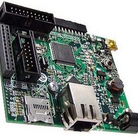
Power Management Modules & Development Tools ST7590 PRIME BRD Narrow-Band OFDM
Manufacturer
STMicroelectronics
Type
Motor / Motion Controllers & Driversr
Datasheet
1.EVALST7590-1.pdf
(43 pages)
Specifications of EVALST7590-1
Interface Type
Ethernet
Product
Power Management Development Tools
For Use With/related Products
ST7590
Lead Free Status / RoHS Status
Lead free / RoHS Compliant


Configuration
5
5.1
10/43
Configuration
Ethernet
An Ethernet PHY U5 is available on the board. It is connected through the media
independent interfaces (MII, and reduced MII, RMII) to the Ethernet MACs of the STM32™
microcontroller.
If the Ethernet PHY is used, the crystal resonator X2 must be chosen as STM32 clock
source.
The clock source for the PHY is the clock output MCO signal of the STM32 microcontroller.
To operate in MII mode, the MCO signal must be configured to output 25 MHz, for RMII,
50 MHz.
By default the MII address of the Ethernet PHY is 0x01 and the initial configuration of the
Ethernet PHY is selected as shown in
Table 2.
There are two LEDs embedded in RJ45 connector (CN5) which are used to indicate the
status of the line:
●
●
The “Serial Management Interface” (SMI) is part of the MII interface and is used to transfer
management information between MAC and PHY (access of the PHY registers).
The PHY can communicate with the STM32 microcontroller over MII or RMII. SB1, SB2 and
SB3 must be configured according to the mode chosen. MII is chosen as a default option.
Table 3.
Auto negotiation
10/100 Mb
Half/full duplex
Internal loopback
Power-down
MII/RMII mode
The green LED in the connector is switched on continuously when the Ethernet link is
established with the counterpart.
The yellow LED in the connector blinks when a transmission or a reception is ongoing.
Function
Function
Default configuration of the Ethernet PHY
Ethernet PHY configuration defined by SB1, SB2 and SB3
SB1
SB2
SB3
Doc ID 17009 Rev 1
Enabled
100 Mb selected for auto negotiation advertisement
Full duplex selected for auto negotiation advertisement
Disabled
Disabled (PHY is not in power-down)
MII selected
Table
Fit 0 Ω resistor
Removed
Removed
MII
2.
Default configuration
Fit 0 Ω resistor
Fit 0 Ω resistor
Removed
RMII
UM0896
Related parts for EVALST7590-1
Image
Part Number
Description
Manufacturer
Datasheet
Request
R

Part Number:
Description:
STMicroelectronics [RIPPLE-CARRY BINARY COUNTER/DIVIDERS]
Manufacturer:
STMicroelectronics
Datasheet:
Part Number:
Description:
STMicroelectronics [LIQUID-CRYSTAL DISPLAY DRIVERS]
Manufacturer:
STMicroelectronics
Datasheet:

Part Number:
Description:
BOARD EVAL FOR MEMS SENSORS
Manufacturer:
STMicroelectronics
Datasheet:
Part Number:
Description:
NPN TRANSISTOR POWER MODULE
Manufacturer:
STMicroelectronics
Datasheet:
Part Number:
Description:
TURBOSWITCH ULTRA-FAST HIGH VOLTAGE DIODE
Manufacturer:
STMicroelectronics
Datasheet:
Part Number:
Description:
Manufacturer:
STMicroelectronics
Datasheet:
Part Number:
Description:
DIODE / SCR MODULE
Manufacturer:
STMicroelectronics
Datasheet:
Part Number:
Description:
DIODE / SCR MODULE
Manufacturer:
STMicroelectronics
Datasheet:
Part Number:
Description:
Search -----> STE16N100
Manufacturer:
STMicroelectronics
Datasheet:
Part Number:
Description:
Search ---> STE53NA50
Manufacturer:
STMicroelectronics
Datasheet:
Part Number:
Description:
NPN Transistor Power Module
Manufacturer:
STMicroelectronics
Datasheet:
Part Number:
Description:
DIODE / SCR MODULE
Manufacturer:
STMicroelectronics
Datasheet: