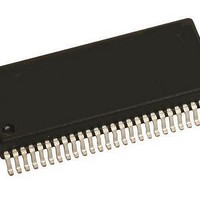
KIT33937AEKEVBE Freescale Semiconductor, KIT33937AEKEVBE Datasheet - Page 15

KIT33937AEKEVBE
Manufacturer Part Number
KIT33937AEKEVBE
Description
Power Management Modules & Development Tools 3-PHASE FET PRE-DRIV
Manufacturer
Freescale Semiconductor
Type
MOSFET & Power Driverr
Datasheet
1.MCZ33937AEKR2.pdf
(48 pages)
Specifications of KIT33937AEKEVBE
Interface Type
SPI
Product
Power Management Modules
Silicon Manufacturer
Freescale
Silicon Core Number
MC33937
Kit Application Type
Power Management
Application Sub Type
FET Driver
Kit Contents
Board, CD
Rohs Compliant
Yes
For Use With/related Products
MC33937
Table 5. Dynamic Electrical Characteristics (continued)
values noted reflect the approximate parameter means at T
Analog Integrated Circuit Device Data
Freescale Semiconductor
GATE DRIVE (CONTINUED)
OVER-CURRENT COMPARATOR
DESATURATION DETECTOR AND PHASE COMPARATOR
CURRENT SENSE AMPLIFIER
Notes
Duty Cycle
100% Duty Cycle Duration
Maximum Programmable Deadtime
Over-current Protection Filter Time
Rise Time (OC_OUT)
Fall Time (OC_OUT)
Phase Comparator Propagation Delay Time to 50% of V
Phase Comparator Match (Prop Delay Mismatch of Three Phases)
Desaturation and Phase Error Blanking Time
Desaturation Filter Time (Filter Time is digital)
Output Settle Time to 99%
43.
44.
45.
46.
47.
Characteristics noted under conditions 8.0 V
10% - 90%
C
90% - 10%
C
Rising Edge Delay
Falling Edge Delay
C
Fault Must be Present for This Time to Trigger
RL = 1.0 k , C
L
L
L
= 100 pF
= 100 pF
= 100 pF
This parameter is guaranteed by design, not production tested.
Maximum duty cycle is actually 100% because there is an internal charge pump to maintain the gate voltage in the 100% on condition.
However, in high duty cycle cases, there may not be sufficient time to recharge the bootstrap capacitors during the off time. Large
bootstrap capacitors will allow high duty cycles to be obtained for a short time. For applications needing closer to 100% duty cycle,
external diodes may optionally be used to provide high peak current charging capability to the bootstrap capacitors. These diodes would
be connected between VLS and the Px_BOOTSTRAP pins. In applications with lower gate charge requirements, the maximum duty
cycle can also be increased.
A Minimum Deadtime of 0.0 can be set via an SPI command. When Deadtime is set via a DEADTIME command, a minimum of 1 clock
cycle duration and a maximum of 255 clock cycles is set using the internal time base clock as a reference. Commands exceeding this
value limits at this value.
Blanking time, t
system noise during the switching event.
Without considering any offsets such as input offset voltage, internal mismatch and assuming no tolerance error in external resistors.
(43),
(44)
(43)
L
= 500 pF, 0.3 V < V
BLANK
(43),
(43),
, is applied to all phases simultaneously when switching ON any output FET. This precludes false errors due to
Characteristic
(44)
(47)
(45)
O
< 4.8 V, Gain = 5 to 15
(46)
(43)
V
PWR
DD
; C
=
L
V
SUP
A
100 pF
= 25°C under nominal conditions, unless otherwise noted.
40 V, -40 C
Symbol
t
t
t
SETTLE
MATCH
BLANK
t
t
t
t
t
t
MAX
t
ROC
FOC
FILT
OC
DC
DC
t
t
R
F
T
A
DYNAMIC ELECTRICAL CHARACTERISTICS
135 C, unless otherwise noted. Typical
10.2
Min
640
0.0
0.9
4.7
10
10
–
–
–
–
–
ELECTRICAL CHARACTERISTICS
Typ
937
7.1
1.0
15
–
–
–
–
–
–
–
–
Unlimited
1231
Max
19.6
240
200
200
350
100
3.5
9.1
2.0
96
Unit
µs
µs
ns
ns
ns
ns
µs
ns
µs
%
s
33937
15


