MPM-DC-KIT Actel, MPM-DC-KIT Datasheet - Page 3
MPM-DC-KIT
Manufacturer Part Number
MPM-DC-KIT
Description
Power Management Modules & Development Tools Mixed signal Power Manager Kit
Manufacturer
Actel
Type
DC/DC Switching Converters, Regulators & Controllersr
Datasheet
1.MPM-DC-KIT.pdf
(4 pages)
Specifications of MPM-DC-KIT
Input Voltage
1.5 V to 5 V
Output Voltage
0 V to 3.3 V
Interface Type
I2C, JTAG
Operating Supply Voltage
9 V
Product
Power Management Modules
For Use With/related Products
AFS090
Lead Free Status / RoHS Status
Lead free / RoHS Compliant


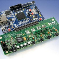
Mixed Signal Power Manager Daughter Card Kit Quickstart Card
Software for MPM Demo Design
Download the MPM Executable which contains the demo design from the Actel website:
http://www.actel.com/products/hardware/devkits_boards/mpm_dc.aspx.
Run the demo design executable. This will install the MPM GUI. From the MPM GUI you can
program the demo design into the SmartFusion device and configure your power sequence or
trimming. You can update the sequence by uploading only the NVM register locations after the first
time you program the main design to the board.
Running the MPM Demo Design
With the SmartFusion Evaluation Kit – Connect the MPM daughter card to the A2F-EVAL-KIT
board. Connect both USB cables from your PC to the evaluation kit. One USB provides power and
UART connection; the other provides the programming connection. If you are using the daughter
card with the evaluation kit, you can remove the plastic legs and add the rubber feet supplied for this
purpose.
With the SmartFusion Development Kit – Connect the MPM daughter card to the A2F-DEV-KIT
board. Connect the 9 V power supply to the MPM Daughter Card and the 5 V power supply to the
development kit. It is a good idea to double check the voltages before connecting the supplies.
Connect the low-cost programming stick to the development kit and connect with a USB cable to the
PC for programming. Also connect the other USB cable to the USB connection on the board and to
your PC.
From the MPM GUI, select File > Write Device to load the MPM design to the device for the first
time. Use the switches on the evaluation or development kit to activate the power-up sequence. You
can then create interrupts and change POT settings to review the performance of the board. The
OLED shows the voltage of each of the first four power rails.
• SW1 initiates MPM power-up or power-down, depending on current state
• SW2 moves to the next OLED "screen" (e.g., next channel details)
To change the power sequence, use the GUI to change the settings and then do File > Write NVM to
update the register settings. It is not necessary to write the device again.
The demo design has many capabilities. To fully understand and use power management,
please refer to the documentation.
3
Related parts for MPM-DC-KIT
Image
Part Number
Description
Manufacturer
Datasheet
Request
R

Part Number:
Description:
Resistor Network,Thin Film,10KOhms,100WV,.1+/-% Tol,-25,25ppm-TC,1105-Case
Manufacturer:
Vishay
Part Number:
Description:
Resistor Network,Thin Film,10KOhms,100WV,1+/-% Tol,-25,25ppm-TC,1105-Case
Manufacturer:
Vishay

Part Number:
Description:
Compact, 10w Pc Mount Single, Dual & Triple Out Ac/dc Power Supplies
Manufacturer:
MicroPower Direct, LLC
Datasheet:
Part Number:
Description:
Board Mount, 10w Single & Dual Output Ac/dc Power Supplies
Manufacturer:
MicroPower Direct, LLC
Datasheet:
Part Number:
Description:
Ery Low Cost, 10w Compact ?power Brick? Ac/dc Power Supplies
Manufacturer:
MicroPower Direct, LLC
Datasheet:
Part Number:
Description:
Very Low Cost, 10w Compact Power Brick Ac/dc Power Supplies
Manufacturer:
MicroPower Direct, LLC
Datasheet:
Part Number:
Description:
Compact, 15w Pc Mount Single, Dual & Triple Out Ac/dc Power Supplies
Manufacturer:
MicroPower Direct, LLC
Datasheet:
Part Number:
Description:
Board Mount, 15w Single, Dual & Triple Out Ac/dc Power Supplies
Manufacturer:
MicroPower Direct, LLC
Datasheet:
Part Number:
Description:
Chassis Mount, 15w Single, Dual & Triple Out Ac/dc Power Supplies
Manufacturer:
MicroPower Direct, LLC
Datasheet:
Part Number:
Description:
Compact, Board Mount 4w Single And Dual Output Ac/dc Power Supplies
Manufacturer:
MicroPower Direct, LLC
Datasheet:

Part Number:
Description:
MCU, MPU & DSP Development Tools Silicon Sculptor Programming Mod
Manufacturer:
Actel
Part Number:
Description:
MCU, MPU & DSP Development Tools InSystem Programming ProASICPLUS Devices
Manufacturer:
Actel
Part Number:
Description:
Programming Socket Adapters & Emulators PQ160 Module
Manufacturer:
Actel
Part Number:
Description:
Programming Socket Adapters & Emulators Axcelerator Adap Module Kit
Manufacturer:
Actel
Part Number:
Description:
Programming Socket Adapters & Emulators Evaluation
Manufacturer:
Actel