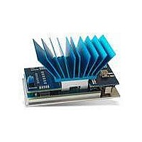
TE-POWER-PLUS Micropelt, TE-POWER-PLUS Datasheet - Page 9

TE-POWER-PLUS
Manufacturer Part Number
TE-POWER-PLUS
Description
Power Management Modules & Development Tools SM THERMAL ENERGY HARVESTING DEV KIT
Manufacturer
Micropelt
Type
Energy Harvestingr
Datasheet
1.TE-POWER-PLUS.pdf
(10 pages)
Specifications of TE-POWER-PLUS
Input Voltage
0.27 V to 2 V
Output Voltage
1.6 V to 5 V
Board Size
63 mm x 30 mm x 34 mm
Maximum Operating Temperature
+ 105 C
Product
Power Management Modules
Dimensions
63 mm x 30 mm x 34 mm
Lead Free Status / RoHS Status
Lead free / RoHS Compliant
Available stocks
Company
Part Number
Manufacturer
Quantity
Price
Company:
Part Number:
TE-POWER-PLUS
Manufacturer:
Micropelt
Quantity:
135
6. Application of the TE-Power PLUS
6.1 Attaching the Assembly to a Harvesting Target
Attachment of a thermoharvester to its target heat source is a critical factor in any application. The TE-Power PLUS
helps to explore the effects of mounting pressure, surface flatness / roughness and various thermal interfaces
materials on the harvesting result. The base of the assembly attaches to the target either through magnetic force
or through 2 tapped mounting holes (M2.5).
6.2 Heatsink Positioning and Orientation
Both positioning and orientation of the TE-Power PLUS are of major importance for the power yield, particularly
when the power density of the heat source is low. The alignment of the heatsink fins relative to the heat source
and the direction of natural convection deserves special attention. To help optimize this, the heatsink adaptor has
been designed so that the heatsink can be removed and then re-attached perpendicular to its default orientation.
Note that it is inefficient to place the TE-Power PLUS horizontally on top of a heat source (Figure A). A forced air
flow over the heatsink however maximizes power, regardless of position and orientation.
6.3 Radiation Suppression
Hot surfaces radiate in the infrared spectrum. This can cause the TE-Power PLUS’s heatsink to heat up, diminishing
effective ΔT and thus the power output of the device. In such cases it may be helpful to cover the hot surface near
the TE-Power PLUS such that radiation is inhibited. Alternatively, a block of thermally conductive material may be
used to increase the distance between radiating surface and heatsink, thereby improving natural convection.
6.4 Thermal Path Optimization
The standard heatsink of the TE-Power ONE and PLUS is a compromise between physical size and thermal per-
formance. The heatsink is an off-the-shelf part, selected for good performance with lower temperature gradients.
For high temperature gradients and any cutting edge application the heatsink should be re-considered and tested
against other makes, sizes and shapes.
To facilitate the attachment and evaluation of different heatsink designs, the aluminum heatsink adaptor features
4 tapped holes (M1.6). This allows for thorough and comprehensive exploration of the thermal path under varying
thermal conditions. A more suitable heatsink will, under otherwise identical conditions, stay cooler. Both the cold
side temperature measured by Pt100 and the power yield of the TEG will reflect this. The output voltage and
power will both increase accordingly.
www.micropelt.com | phone +49 761 156 337 0 | info@micropelt.com
Figure A: Inferior positioning
TE-Power PLUS mounted atop the heat
source with the heatsink in a bubble of hot
air. This arrangement yields low ΔT and low
power output.
Figure B: Preferred positioning
TE-Power PLUS mounted on a
heatsink fins aligned horizon-
tally. Results in acceptable per-
formance.
vertical surface with the
Convection Stream
Figure C: Ideal positioning
TE-Power PLUS mounted on a vertical
surface with the heatsink fins aligned
vertically. This is best supporting natural
convection and results in the highest
possible ΔT and power output.
0037DSTPP75x0310v5e |
Page 9


