EE-SPY301 Omron, EE-SPY301 Datasheet
EE-SPY301
Specifications of EE-SPY301
Available stocks


Related parts for EE-SPY301


EE-SPY301 Summary of contents
Page 1
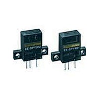
... Appearance Sensing method Sensing distance Diffuse 5 mm Horizontal Vertical J ACCESSORIES Name Solder connector Connector with 1 m cable Connector holder for EE-1003 Output configuration Weight Dark-ON Approx. 2.6 g Light-ON Dark-ON Light-ON Part number EE-1002 EE-1003 EE-1003A Part number EE-SPY301 EE-SPY401 EE-SPY302 EE-SPY402 ...
Page 2
... Specifications J RATINGS Item Reflective EE-SPY301 Supply voltage VDC ±10%, ripple (p-p): 5% max. Current consumption Average max.; Peak max. Rated sensing distance 5 mm (Reflection factor: 90%; white paper mm) Standard reference object Transparent, opaque Differential distance 0.2 mm (with a sensing distance of 3 mm, horizontally) Control output ...
Page 3
... Engineering Data J OPERATING RANGE (TYPICAL) EE-SPY301, EE-SPY401 12 Operates 11 Releases 10 Reference Y object: White paper ( mm) (reflection factor: 90 (mm) EE-SPY302, EE-SPY402 Reference object: White paper ( mm) (reflection factor: 90 (mm) J SENSING DISTANCE VS. OBJECT AREA (TYPICAL) EE-SPY301/SPY302/SPY401/SPY402 Reference object: White paper (reflection factor: 90 Sensing area l ( EE-SPY301, EE-SPY401 ...
Page 4
... J SENSING ANGLE VS. SENSING DISTANCE (TYPICAL) Vcc = 24 V Length of cable Reference object: Thickness of cable White paper 2 0 mm) EE-SPY301 (reflection factor: EE-SPY302 90%) d −θ d −θ +θ +θ Angle θ (°) Operation J INTERNAL/EXTERNAL CIRCUIT DIAGRAM Light-ON/Dark-ON Operation indicator 1.5 to Load 3 mA ...
Page 5
... Dimensions Unit: mm (inch) J EE-SPY301, EE-SPY401 26 (1.02) 7 (0.28 (0.55) (0.79) 6 (0.24) 3(0.12) 7.5 (0.30) (3) 2.5 (0.10) J EE-SPY302, EE-SPY402 26 (1.02) 14 3.5 (0.55) (0.14) 7 (0.28) (0.31) 20 (0.79) 6 (0.24) 3(0.12) 7.5 (0.30) (3) 2.5 (0.10) (0.20 (0.79) 14 (0.55) 8 Sensing face (0.31) 4 (0.16) Operation indicator Two, 3.2 dia. ...
Page 6
... J EE-1002 CONNECTOR 16.72 6 (0.24) (0.24) 3 (0.12) 16 (0.63) 5.5 (0.22) 1.2 (0.05) 0.6 t0.25 (0.02) 4 2.5 (0.16) 11.5 (0.45) 13.5 (0.53) J EE-SPY301 + EE-1003 20 (0.79) 10.7 (0.42) J EE-1003 CONNECTOR 6 21.5 (0.85) 10.7 (0.42) 6 (0.24) 1.2 (0.05) 1,000± EE-1003A CONNECTOR HOLDER 5.7 (0.22 ...
Page 7
... Connector or EE-1003 Connector (with a 1-m cable attached) to connect the cable to the output terminals. Use the EE1003A Connector Holder to prevent accidental disconnection of the EE-1003 Connector from the EE-SPY301/401/302/402 Photomicrosensor. Do not impose excessive force on the terminals (refer to the diagram below). Excess force will damage the terminals. No ...