BPV11F Vishay, BPV11F Datasheet - Page 2
BPV11F
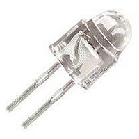
Manufacturer Part Number
BPV11F
Description
Photodetector Transistors 15 Degree 150mW
Manufacturer
Vishay
Type
IR Chipr
Specifications of BPV11F
Maximum Power Dissipation
150 mW
Maximum Dark Current
50 nA
Collector- Emitter Voltage Vceo Max
70 V
Maximum Operating Temperature
+ 100 C
Package / Case
T-1 3/4
Transistor Polarity
NPN
Wavelength Typ
930nm
Power Consumption
150mW
Viewing Angle
15°
No. Of Pins
2
Light Current
9mA
Dark Current
50nA
C-e Breakdown Voltage
70V
Current Rating
50mA
Voltage - Collector Emitter Breakdown (max)
70V
Current - Collector (ic) (max)
10mA
Current - Dark (id) (max)
50nA
Wavelength
930nm
Power - Max
150mW
Mounting Type
Through Hole
Orientation
Top View
Transistor Case Style
T-1 3/4 (5mm)
Svhc
No SVHC (20-Jun-2011)
Current Ic Typ
9mA
Rohs Compliant
Yes
Phototransistor Type
Phototransistor
Polarity
NPN
Number Of Elements
1
Collector-emitter Voltage
70V
Collector Current (dc) (max)
50mA
Collector-emitter Sat Volt (max)
0.3V
Dark Current (max)
50nA
Power Dissipation
150mW
Peak Wavelength
930nm
Half-intensity Angle
30deg
Mounting
Through Hole
Pin Count
2
Package Type
T-1 3/4
Lead Free Status / RoHS Status
Lead free / RoHS Compliant
Lead Free Status / RoHS Status
Lead free / RoHS Compliant, Lead free / RoHS Compliant
Available stocks
Company
Part Number
Manufacturer
Quantity
Price


BPV11F
Vishay Semiconductors
Electrical Characteristics
T
Optical Characteristics
T
Typical Characteristics
T
www.vishay.com
2
Collector Emitter Breakdown
Voltage
Collector-emitter dark current
DC Current Gain
Collector-emitter capacitance
Collector - base capacitance
Collector Light Current
Angle of Half Sensitivity
Wavelength of Peak Sensitivity
Range of Spectral Bandwidth
Collector Emitter Saturation
Voltage
Turn-On Time
Turn-Off Time
Cut-Off Frequency
amb
amb
amb
Figure 1. Total Power Dissipation vs. Ambient Temperature
= 25 °C, unless otherwise specified
= 25 °C, unless otherwise specified
= 25 °C unless otherwise specified
94 8300
200
160
120
80
40
Parameter
Parameter
0
0
T
amb
20
– Ambient Temperature (°C)
40
I
V
V
V
V
E
V
E
V
V
V
C
I
60
C
CE
CE
CE
CB
e
CE
e
S
S
S
= 1 mA
= 1 mW/cm
= 1 mW/cm
= 1 mA
= 5 V, I
= 5 V, I
= 5 V, I
= 10 V, E = 0
= 5 V, I
= 0 V, f = 1 MHz, E = 0
= 0 V, f = 1 MHz, E = 0
= 5 V
R
thJA
80
Test condition
Test condition
C
C
C
C
= 5 mA, R
= 5 mA, R
= 5 mA, R
= 5 mA, E = 0
2
2
100
, λ = 950 nm,
, λ = 950 nm,
L
L
L
= 100 Ω
= 100 Ω
= 100 Ω
V
Symbol
Symbol
V
(BR)CEO
C
C
I
λ
CEO
h
CEsat
t
t
I
CEO
CBO
λ
ϕ
on
off
f
FE
ca
0.5
Figure 2. Collector Dark Current vs. Ambient Temperature
c
p
94 8249
10
10
10
10
10
4
3
2
1
20
Min
Min
70
3
T
amb
40
- Ambient Temperature (°C)
V
CE
900 to 980
= 10 V
± 15
Typ.
Typ.
450
930
130
110
15
19
1
9
6
5
60
Document Number 81505
80
Max
Max
300
50
Rev. 1.5, 13-Nov-06
100
Unit
Unit
deg
kHz
mA
mV
nm
nm
nA
pF
pF
μs
μs
V
Related parts for BPV11F
Image
Part Number
Description
Manufacturer
Datasheet
Request
R

Part Number:
Description:
Photodetector Transistors NPN Phototransistor 80V 150mW 450-1080nm
Manufacturer:
Vishay
Datasheet:

Part Number:
Description:
Photodetector Transistors PHOTODIODE
Manufacturer:
OSRAM Opto Semiconductors Inc
Part Number:
Description:
Photodetector Transistors PHOTODIODE
Manufacturer:
OSRAM Opto Semiconductors Inc

Part Number:
Description:
357-036-542-201 CARDEDGE 36POS DL .156 BLK LOPRO
Manufacturer:
Vishay
Datasheet:
Part Number:
Description:
357-036-542-201 CARDEDGE 36POS DL .156 BLK LOPRO
Manufacturer:
Vishay
Datasheet:
Part Number:
Description:
357-036-542-201 CARDEDGE 36POS DL .156 BLK LOPRO
Manufacturer:
Vishay
Datasheet:
Part Number:
Description:
357-036-542-201 CARDEDGE 36POS DL .156 BLK LOPRO
Manufacturer:
Vishay
Datasheet:
Part Number:
Description:
357-036-542-201 CARDEDGE 36POS DL .156 BLK LOPRO
Manufacturer:
Vishay
Datasheet:
Part Number:
Description:
357-036-542-201 CARDEDGE 36POS DL .156 BLK LOPRO
Manufacturer:
Vishay
Datasheet:
Part Number:
Description:
357-036-542-201 CARDEDGE 36POS DL .156 BLK LOPRO
Manufacturer:
Vishay
Datasheet:
Part Number:
Description:
357-036-542-201 CARDEDGE 36POS DL .156 BLK LOPRO
Manufacturer:
Vishay
Datasheet:
Part Number:
Description:
357-036-542-201 CARDEDGE 36POS DL .156 BLK LOPRO
Manufacturer:
Vishay
Datasheet:
Part Number:
Description:
357-036-542-201 CARDEDGE 36POS DL .156 BLK LOPRO
Manufacturer:
Vishay
Datasheet:
Part Number:
Description:
357-036-542-201 CARDEDGE 36POS DL .156 BLK LOPRO
Manufacturer:
Vishay
Datasheet:
Part Number:
Description:
357-036-542-201 CARDEDGE 36POS DL .156 BLK LOPRO
Manufacturer:
Vishay
Datasheet: