TSL2550D TAOS, TSL2550D Datasheet - Page 8
TSL2550D
Manufacturer Part Number
TSL2550D
Description
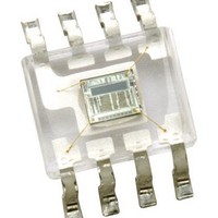
Industrial Optical Sensors Ambient Light Sensor SMBus
Manufacturer
TAOS
Type
Ambient Light Sensor with Digital Outputr
Datasheet
1.TSL2550D.pdf
(20 pages)
Specifications of TSL2550D
Product
Ambient Light Sensor
Maximum Operating Temperature
+ 85 C
Minimum Operating Temperature
- 40 C
Lead Free Status / RoHS Status
Lead free / RoHS Compliant
Other names
TSL2550D-TR


TSL2550
AMBIENT LIGHT SENSOR
WITH SMBus INTERFACE
TAOS029L − OCTOBER 2007
Command Register
ADC Register
8
Copyright E 2007, TAOS Inc.
The command register is used primarily to:
D
D
D
Table 1 shows the six primary commands used to control the TSL2550.
The content of the command register defaults to 0x00h when power is applied to the device, placing the device
into the power-down mode.
Once the TSL2550 is set to the standard range mode (0x18h) or the extended range mode (0x1Dh), the device
remains in that mode until it is powered down or the mode is changed via the command register.
The 0x03h command has two purposes: It is used to power up the device and can also be used to check that
the device is communicating properly. The value returned during a read cycle should be 0x03h.
The TSL2550 contains two ADC registers (channel 0 and channel 1). Each ADC register contains two
component fields that are used to determine the logarithmic ADC count value: CHORD bits and STEP bits. The
CHORD bits correspond to the most significant portion of the ADC value and specifies a segment of the
piece-wise linear approximation. The STEP bits correspond to the least significant portion of the ADC count
value and specifies a linear value within a segment. CHORD and STEP bits all equal to 0 corresponds to a
condition in which the light level is below the detection limit of the sensor. CHORD and STEP bits all equal to
1 corresponds to an overflow condition.
Each of the two ADC value registers contain seven data bits and a valid bit as described in Table 2.
Select which ADC register will be read during a read cycle
Switch the dynamic range of the device between standard and extended range modes
Power the device up for operation or power it down for minimum power consumption
CHORD
VALID
VALID
FIELD
VALID
STEP
B7
COMMAND
0x1Dh
0x00h
0x03h
0x18h
0x43h
0x83h
6 to 4
3 to 0
BITS
7
B6
C2
ADC channel data is valid. One indicates that the ADC has written data into the
channel data register, since ADCEN was asserted in the COMMAND register.
CHORD number.
STEP number.
CHORD BITS
Power-down state
Power-up state/Read command register
Write command to assert extended range mode
Write command to reset or return to standard range mode
Read ADC channel 0
Read ADC channel 1
Table 2. ADC Register Data Format
B5
C1
r
Table 1. Command Summary
www.taosinc.com
B4
C0
DESCRIPTION
B3
S3
FUNCTION
B2
S2
STEP BITS
r
B1
S1
The LUMENOLOGY r Company
B0
S0
Related parts for TSL2550D
Image
Part Number
Description
Manufacturer
Datasheet
Request
R

Part Number:
Description:
Microcontroller Modules & Accessories TAOS Eval Module w/USB Interface
Manufacturer:
TAOS
Part Number:
Description:
Optical Sensor Development Tools TAOS Eval Module
Manufacturer:
TAOS

Part Number:
Description:
Industrial Optical Sensors Ambient Light Sensor SMBus
Manufacturer:
TAOS
Datasheet:

Part Number:
Description:
Photodiodes TriColor Sensor RGB, Clear Ch
Manufacturer:
TAOS
Datasheet:

Part Number:
Description:
LED Displays Hexadecimal Display 4-bit
Manufacturer:
TAOS
Datasheet:

Part Number:
Description:
Photodiodes Linear Sensor Array 200dpi 64pix
Manufacturer:
TAOS
Datasheet:

Part Number:
Description:
Photodiodes Linear Array 200 DPI
Manufacturer:
TAOS
Datasheet:

Part Number:
Description:
Photodiodes Light to Voltage Converter
Manufacturer:
TAOS
Datasheet:

Part Number:
Description:
Photodiodes Linear Array 200 DPI
Manufacturer:
TAOS
Datasheet:

Part Number:
Description:
Photodiodes Light to Voltage Converter
Manufacturer:
TAOS
Datasheet:
Part Number:
Description:
Industrial Optical Sensors Ambient Light Sensor SMBus
Manufacturer:
TAOS
Datasheet:
Part Number:
Description:
Photodiodes TriColor Sensor RGB, Clear Ch
Manufacturer:
TAOS
Datasheet:
Part Number:
Description:
LED Displays Hexadecimal Display 4-bit
Manufacturer:
TAOS
Datasheet:
Part Number:
Description:
Photodiodes Linear Sensor Array 200dpi 64pix
Manufacturer:
TAOS
Datasheet:
