EA LED78x64-E ELECTRONIC ASSEMBLY, EA LED78x64-E Datasheet - Page 6
EA LED78x64-E
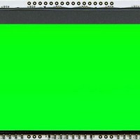
Manufacturer Part Number
EA LED78x64-E
Description
LCD Graphic Display Modules & Accessories Grn LED Backlight For DOG-XL Series
Manufacturer
ELECTRONIC ASSEMBLY
Datasheet
1.EA_DOGXL160E-7.pdf
(8 pages)
Specifications of EA LED78x64-E
Pixel Density
160 x 104
Fluid Type
STN
Module Size (w X H X T)
78 mm x 64 mm x 3.6 mm
Viewing Area (w X H)
72 mm x 45 mm
Backlighting
Green
Background Color
Green
Operating Temperature Range
- 20 C to + 70 C
Interface
SPI
Display Mode
Transmissive
Lead Free Status / RoHS Status
Lead free / RoHS Compliant


EA DOG
Page 6
GRAPHIC RAM
The
represents 4 dots on display.
You will find more information in the datasheet of the
UC1610 controller, which is on our website at
http://www.lcd-module.de/eng/pdf/zubehoer/uc1610.pdf
UC1610 PROGRAMMING COMMANDS (ESSENCE)
INITIALISATION EXAMPLE (6 O’ CLOCK)
12:00 VIEWING ANGLE, TOP VIEW OPTION
If the display is read mostly from above (on the front of
a laboratory power supply unit, for example), the
preferred angle of viewing can be set to 12 o’clock. This
rotates the display by 180°. A slightly different
initialization setup is required for this.
Command
Command
(12) Set Display Enable
(30) Set Window Start Column
(31) Set Window Start Page
(32) Set Window End Column
(33) Set Window End Page
(34) Set Window Enable
(19) Set LCD Mapping Control
(19) Set LCD Mapping Control
(13) Set RAM Address Control
(27) Set COM End
(24) Set LCD Bias Ratio
(11) Set Vbias Potentiometer
(13) Set RAM Address Control
(18) Set Display Enable
(1)
(4)
(7)
(9)
(6) Set Panel Loading
EA DOG
Write Data Byte
Set Column Address LSB
Set Column Address MSB
Set Page Address
Set Scroll Line LSB
Set Scroll Line MSB
Command
XL
XL
160-7 has an internal RAM, each Byte
160-7
Initialisation example (changes for top view )
CD
CD
CD
Initialisation example (bottom view)
1
0
0
0
0
0
0
0
0
0
0
0
0
0
0
0
0
0
0
D7
D7
D7
0
0
0
1
1
1
1
0
1
1
0
1
1
0
1
0
0
0
1
1
0
1
1
1
D6
D6
D6
0
0
1
0
0
1
1
0
1
1
0
1
1
1
1
1
1
0
1
0
1
0
0
1
Command Code
D5
D5
D5
0
0
1
1
0
1
1
0
1
1
0
1
1
1
0
0
0
1
1
0
0
0
1
0
data bit D[7..0]
WPC0[7..0]
WPC1[7..0]
D4
D4
D4
0
1
0
0
1
1
1
1
1
1
0
0
0
1
0
0
0
1
0
0
0
D3
D3
D3
1
1
0
0
0
0
1
0
0
0
0
0
1
1
0
1
1
1
0
WPP0[4..0]
WPP1[4..0]
PA[4..0]
CA[3..0]
CA[7..4]
D2
D2
D2
1
1
1
1
1
0
0
1
0
0
0
0
0
0
1
0
1
1
AC[2..0]
D1
D1
D1
1
0
0
1
1
0
0
1
0
0
0
1
1
0
1
0
1
1
C2
C4
D0
D0
D0
0
1
0
1
1
1
0
0
0
1
1
1
1
1
1
0
6 o’clock (Bottom View)
Write one byte to memory
Set the SRAM column address
CA=0..159
Set the SRAM page address PA=0..25
C2=0: disable Display (sleep)
C2=1: enable Display (exit from sleep)
AC0: 0=stop increment at end ,1=warp around
AC1: 0=column, 1=page increment
AC2: Set page increment: 0= +1, 1= -1
Set Start Column of Window Function
Set Start Page of Window Function
Set End Column of Window Function
Set End Page of Window Function
C4: 0=disable, 1=enable Window Function
(disable before changing column and pages)
$EB
$F1
$67
$C0
$40
$50
$2B
$81
$5F
$89
$AF
$C6
Hex
Hex
Remark
Set last COM electrode to 103
(number of COM electrodes - 1)
SEG (column) and COM (row) normal
Set Display Startline to 0
Set Panelloading to 28..38nF
Set Bias to 1/12
Set Contrast
Set Auto-Increment
Display on
Remark
SEG (column) and COM (row) mirror
Function
ELECTRONIC ASSEMBLY reserves
the right to change specifications
without prior notice. Printing and
typographical
Bit
D0
D1
D2
D3
D4
D5
D6
D7
1
2
3
4
Dot
8-Bit = 4-Dots
00 = off
11 = on
00 = off
11 = on
00 = off
11 = on
00 = off
11 = on
12 o’clock (Top View)
errors
Example Hex
reserved.
1
1
0
0
0
0
1
1
$C3
Related parts for EA LED78x64-E
Image
Part Number
Description
Manufacturer
Datasheet
Request
R

Part Number:
Description:
Display Modules & Development Tools Starter/Demoboard Windows USB For DOGM
Manufacturer:
ELECTRONIC ASSEMBLY

Part Number:
Description:
Display Modules & Development Tools Starter/Demoboard DOGM/ Windows USB
Manufacturer:
ELECTRONIC ASSEMBLY
Datasheet:

Part Number:
Description:
LCD Character Display Modules 4x20 Yellow/Green RS-232 Interface
Manufacturer:
ELECTRONIC ASSEMBLY
Part Number:
Description:
LCD Character Display Modules 4x20 Blue-White RS-232 Interface
Manufacturer:
ELECTRONIC ASSEMBLY
Part Number:
Description:
LCD Character Display Modules 2x16 Yellow/Green RS-232 Interface
Manufacturer:
ELECTRONIC ASSEMBLY

Part Number:
Description:
LCD Character Display Modules STN(+) Reflective Yel/Grn Background
Manufacturer:
ELECTRONIC ASSEMBLY
Datasheet:

Part Number:
Description:
LCD Character Display Modules STN(-) Transmissive Blue Background
Manufacturer:
ELECTRONIC ASSEMBLY
Datasheet:

Part Number:
Description:
LCD Character Display Modules FSTN(-) Transmissive Black Background
Manufacturer:
ELECTRONIC ASSEMBLY
Datasheet:

Part Number:
Description:
LCD Character Display Modules Yel/Green Contrast Yl/Grn LED Backlight
Manufacturer:
ELECTRONIC ASSEMBLY
Datasheet:

Part Number:
Description:
LCD Character Display Modules STN(+) Transmissive Yel/Grn Background
Manufacturer:
ELECTRONIC ASSEMBLY
Datasheet:

Part Number:
Description:
LCD Touch Panels Touchpanel Analog for DOGM128-6
Manufacturer:
ELECTRONIC ASSEMBLY
Datasheet:
Part Number:
Description:
LCD Touch Panels Touchpanel Analog For DOGS102
Manufacturer:
ELECTRONIC ASSEMBLY
Datasheet:
Part Number:
Description:
LCD Touch Panels Touchpanel Analog For DOGXL160
Manufacturer:
ELECTRONIC ASSEMBLY
Datasheet:
Part Number:
Description:
LCD Touch Panels Touchpanel Analog For DOG-L128-6
Manufacturer:
ELECTRONIC ASSEMBLY
Datasheet:

Part Number:
Description:
LED Displays Bezel 017-xx Series 75.0x24.2/ 91.0x36.4
Manufacturer:
ELECTRONIC ASSEMBLY
Datasheet: