EA LED78x64-E ELECTRONIC ASSEMBLY, EA LED78x64-E Datasheet - Page 2
EA LED78x64-E
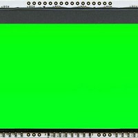
Manufacturer Part Number
EA LED78x64-E
Description
LCD Graphic Display Modules & Accessories Grn LED Backlight For DOG-XL Series
Manufacturer
ELECTRONIC ASSEMBLY
Datasheet
1.EA_DOGXL160E-7.pdf
(8 pages)
Specifications of EA LED78x64-E
Pixel Density
160 x 104
Fluid Type
STN
Module Size (w X H X T)
78 mm x 64 mm x 3.6 mm
Viewing Area (w X H)
72 mm x 45 mm
Backlighting
Green
Background Color
Green
Operating Temperature Range
- 20 C to + 70 C
Interface
SPI
Display Mode
Transmissive
Lead Free Status / RoHS Status
Lead free / RoHS Compliant


EA DOG
Page 2
PINOUT
The EA DO
graphics display, is a new member to
ELECTRONIC
EA DOG series. It also has pins that
allow it to be mounted quickly and
easily.
CONTRAST ADJUSTMENT
The contrast can be set by means of
a command for all the displays in the
EA DOG series. The contrast setting
of the display must be set once by the
software, and is then kept constant
throughout the entire operating temperature range (-20..+70°C), thanks to the integrated temperature
compensation.
LED BACKLIGHT
7 different types are available for individual backlighting:
white, yellow/green, green, blue, red, amber and a full-color
version.
There are 3 separate LED paths available that can be
switched in parallel or in series to suit the system voltage.
To operate the yellow/green (-G), red (-R) and amber (-A)
backlight, an external series resistor can be used to limit
the current. This can be calculated from R=U/I.
To operate the white (-W), green (-E) and blue (-B) backlight,
we recommend a current source (e.g. CAT4238TD) .
The operating life of the yellow/green, red and amber backlights
is 100,000 hours. The white, green and blue backlights we do
provide with long-life LEDs from NICHIA. We recommend that
you dim these or switch them off whenever possible.
Important:
Never connect the backlight LEDs directly to a 5 V/3.3 V
supply as this may immediately destroy the LEDs. Always
use a current limiter. Please note that derating applies at
temperatures exceeding +25°C.
LED-Backlight schematic
G
XL
XL
160, a 160x104-pixel
160-7
ASSEMBLY’s
Pin Symbol Level Function
10
11
12
13
14
15
16
1
2
3
4
5
6
7
8
9
NC
NC
NC
NC
NC
NC
(A1+: LED backlight)
(A2+: LED backlight)
(A3+: LED backlight)
(C1-: LED backlight)
(C2-: LED backlight)
(C3-: LED backlight)
EA LED78x64-G
EA LED78x64-A
EA LED78x64-R
LED backlight
yellow/green
(each path )
amber
red
EA LED78x64-W
Application example: EA LED78x64-W, -E, and -B
EA LED78x64-E
EA LED78x64-B
EA LED78x64-RGB
LED backlight
(each path )
LED backlight
(each color)
green
white
full color
blue
Pin Symbol Level Function
17
18
19
20
21
22
23
24
25
26
27
28
29
30
31
32
Forward
voltage
D3/SDA
D0/SCK
VDD2/3
CS0/A2
VLCD
VB0+
VB1+
VSS2
1.9 V
2.0 V
1.9 V
VB1-
VB0-
VDD
VSS
BM0
RST
typ
CD
D6
ELECTRONIC ASSEMBLY reserves
the right to change specifications
without prior notice. Printing and
typographical
Forward
Current
voltage
H / L Config Serial Interface
H / L L= Command, H= Data
H / L Config Serial Interface
H / L Serial Data
H / L Serial Clock
80 mA
80 mA
80 mA
H
Forward
L
L
L
-
-
-
-
-
max
voltage
4 V
typ
8.8 V
9.0 V
9.1 V
typ
Power LC Drive
Voltage Converter
Voltage Converter
Voltage Converter
Voltage Converter
Power Supply +2,6..3,3V
connect Pin22 <-> Pin23
Power Supply 0V (GND)
connect Pin24 <-> Pin25
Chip Select (active low)
Reset (active low)
Current
@3,3 V
Limiting resistor
60 mA
max
errors
18
18
18
(ohm)
Current
20 mA
20 mA
20 mA
max.
Limiting
resistor
reserved.
(ohm)
@5 V
@5 V
39
39
39
15
Related parts for EA LED78x64-E
Image
Part Number
Description
Manufacturer
Datasheet
Request
R

Part Number:
Description:
Display Modules & Development Tools Starter/Demoboard Windows USB For DOGM
Manufacturer:
ELECTRONIC ASSEMBLY

Part Number:
Description:
Display Modules & Development Tools Starter/Demoboard DOGM/ Windows USB
Manufacturer:
ELECTRONIC ASSEMBLY
Datasheet:

Part Number:
Description:
LCD Character Display Modules 4x20 Yellow/Green RS-232 Interface
Manufacturer:
ELECTRONIC ASSEMBLY
Part Number:
Description:
LCD Character Display Modules 4x20 Blue-White RS-232 Interface
Manufacturer:
ELECTRONIC ASSEMBLY
Part Number:
Description:
LCD Character Display Modules 2x16 Yellow/Green RS-232 Interface
Manufacturer:
ELECTRONIC ASSEMBLY

Part Number:
Description:
LCD Character Display Modules STN(+) Reflective Yel/Grn Background
Manufacturer:
ELECTRONIC ASSEMBLY
Datasheet:

Part Number:
Description:
LCD Character Display Modules STN(-) Transmissive Blue Background
Manufacturer:
ELECTRONIC ASSEMBLY
Datasheet:

Part Number:
Description:
LCD Character Display Modules FSTN(-) Transmissive Black Background
Manufacturer:
ELECTRONIC ASSEMBLY
Datasheet:

Part Number:
Description:
LCD Character Display Modules Yel/Green Contrast Yl/Grn LED Backlight
Manufacturer:
ELECTRONIC ASSEMBLY
Datasheet:

Part Number:
Description:
LCD Character Display Modules STN(+) Transmissive Yel/Grn Background
Manufacturer:
ELECTRONIC ASSEMBLY
Datasheet:

Part Number:
Description:
LCD Touch Panels Touchpanel Analog for DOGM128-6
Manufacturer:
ELECTRONIC ASSEMBLY
Datasheet:
Part Number:
Description:
LCD Touch Panels Touchpanel Analog For DOGS102
Manufacturer:
ELECTRONIC ASSEMBLY
Datasheet:
Part Number:
Description:
LCD Touch Panels Touchpanel Analog For DOGXL160
Manufacturer:
ELECTRONIC ASSEMBLY
Datasheet:
Part Number:
Description:
LCD Touch Panels Touchpanel Analog For DOG-L128-6
Manufacturer:
ELECTRONIC ASSEMBLY
Datasheet:

Part Number:
Description:
LED Displays Bezel 017-xx Series 75.0x24.2/ 91.0x36.4
Manufacturer:
ELECTRONIC ASSEMBLY
Datasheet: