EA KIT160-7LWTK ELECTRONIC ASSEMBLY, EA KIT160-7LWTK Datasheet - Page 5
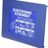
EA KIT160-7LWTK
Manufacturer Part Number
EA KIT160-7LWTK
Description
LCD Graphic Display Modules & Accessories Blue/White Contrast RS-232 Snap-In Kit
Manufacturer
ELECTRONIC ASSEMBLY
Datasheet
1.EA_KIT160-7LWTK.pdf
(20 pages)
Specifications of EA KIT160-7LWTK
Pixel Density
160 x 128
Module Size (w X H X T)
129 mm x 102 mm x 33 mm
Viewing Area (w X H)
92.76 mm x 74.2 mm
Backlighting
LED
Background Color
Blue, White
Attached Touch Screen
Yes
Product
Graphic LCD Module
Style
LCD Graphic Display
Interface
RS-232
Display Mode
Blue Negative
Lead Free Status / RoHS Status
Lead free / RoHS Compliant


DIGITAL INPUTS AND OUTPUTS
All EA KIT160-7 series provide 8 digital In- and 8 outputs (5V
CMOS level, grounded).
8 outputs
Each line can be controlled individually using the "ESC Y W"
command. A maximum current of 10mA can be switched per
line. For more power use an external transistor or MOSFET.
8 inputs
A voltage of >4V starts an internal port macro. However, the
inputs can also be queried and evaluated directly via the
serial interface ("ESC Y R"). When the 8 lines are
combined, up to 256 port macros can thus be addressed.
Each of these port macros can change the contents of the
screen or switch an output, thus enabling a wide range of
control functions. To create the port macros you need a PC
and the EA DISK240 floppy disk. You will find a more
detailed description on page 6. The automatic port query can be disabled by
means of the "ESC Y A 0" command.
Note: The logic circuitry is designed for slow operations; in other words, more than
3 changes per second cannot be easily executed. If an input is left open, it is logical
high (internaly pulled-up via 100 kOhm).
IN- AND OUTPUTS VIA OPTOCOUPLER (EA OPT-OPTO16)
Optionally all In- and Outputs are isolated via
optocouppler circuit (EA OPT-OPTO16 only). The
connection is made via 16 different screw-type terminals.
Direct voltages of 5..35V can be applied at all 8 inputs.
Voltages of over 4V are recognized as high level, while
voltages of under 2V are low level. Voltages of between
2 and 4V are undefined. The polarity is insignificant.
Output is a "open-collector" circuit with collector (+) and
emitter (-) of a NPN transistor. A maximum current of
10mA can be switched per line.
Note: The negative pole of each screw-type terminal can be interconnected by closing the solder straps
LBI1..8 and LBO1..8. These solder straps can also be connected to system ground GND (solder 0Ω strap
R
Note: Logic will be inverted by optocouppler circuit (all inputs left
open: port-macro #255). The command "ESC Y I 1" inverts
logic back again (all inputs left open: port-macro #0)
DEFAULT SETTINGS
After power-on or a manual reset, the registers shown here are
set to a specific value.
Please note that all the settings can be overwritten by creating
a power-on macro (normal macro no. 0).
GND
).
Pin Symbol
11
13
15
17
19
1
3
5
7
9
Register
Text mode
Terminal font
Cursor
Flashing time
User-defined characters
Graphics mode
Graphics font
Last xy
Bar graph 1..16
Clipboard
Select/deselect
Outputs OUT1..8
OUT 1
OUT 2
OUT 3
OUT 4
OUT 5
OUT 6
OUT 7
OUT 8
VDD
GND
EA KIT160-7
J120 Inputs and Outputs
+5V Supply
0V, Ground
Function
Output 1
Output 2
Output 3
Output 4
Output 5
Output 6
Output 7
Output 8
Default settings
Command
ESC L
ESC FT
ESC QC
ESC QZ
ESC E
ESC V
ESC F
ESC W
ESC B
ESC C
ESC K
ESC Y
Pin Symbol
10
12
14
16
18
20
2
4
6
8
GND
VDD
IN 1
IN 2
IN 3
IN 4
IN 5
IN 6
IN 7
IN 8
power-on/reset
Font 3, no zoom
Font 3, no zoom
Low level/open
Undefined
Undefined
Set, black
Selected
0.6 secs
Empty
After
(0;0)
0V, Ground
+5V Supply
Set
On
Function
Input 1
Input 2
Input 3
Input 4
Input 5
Input 6
Input 7
Input 8
5
Related parts for EA KIT160-7LWTK
Image
Part Number
Description
Manufacturer
Datasheet
Request
R

Part Number:
Description:
LCD Graphic Display Modules & Accessories Blue/White Contrast RS-232 w/OPT 9/35V
Manufacturer:
ELECTRONIC ASSEMBLY
Datasheet:

Part Number:
Description:
LCD Graphic Display Modules & Accessories Blue/White Contrast RS-232 Snap-In Kit
Manufacturer:
ELECTRONIC ASSEMBLY
Datasheet:
Part Number:
Description:
Display Development Tools StrEval Kit Blk-Wht w/ Intf Exp and CD
Manufacturer:
ELECTRONIC ASSEMBLY
Datasheet:
Part Number:
Description:
Display Development Tools StrEval Kit Blue-Wht w/ Intf Exp and CD
Manufacturer:
ELECTRONIC ASSEMBLY
Datasheet:
Part Number:
Description:
Display Development Tools StrEval Kit Blue-Wht w/ Intf Exp and CD
Manufacturer:
ELECTRONIC ASSEMBLY
Datasheet:
Part Number:
Description:
KIT LPC3141 SODIMM 66X48 200POS
Manufacturer:
Embedded Artists
Datasheet:
Part Number:
Description:
KIT LPC3152 SODIMM 66X48 200POS
Manufacturer:
Embedded Artists
Datasheet:
Part Number:
Description:
KIT LPC3250 259 WITH QVGA
Manufacturer:
Embedded Artists
Datasheet:

Part Number:
Description:
LCD Graphic Display Modules & Accessories Blue/White Contrast RS-232 Snap-In Kit
Manufacturer:
ELECTRONIC ASSEMBLY
Datasheet:

Part Number:
Description:
LCD Touch Panels Touchpanel Analog for DOGM128-6
Manufacturer:
ELECTRONIC ASSEMBLY
Datasheet:
Part Number:
Description:
LCD Touch Panels Touchpanel Analog For DOGS102
Manufacturer:
ELECTRONIC ASSEMBLY
Datasheet:
Part Number:
Description:
LCD Touch Panels Touchpanel Analog For DOGXL160
Manufacturer:
ELECTRONIC ASSEMBLY
Datasheet:
Part Number:
Description:
LCD Touch Panels Touchpanel Analog For DOG-L128-6
Manufacturer:
ELECTRONIC ASSEMBLY
Datasheet:

Part Number:
Description:
LED Displays Bezel 017-xx Series 75.0x24.2/ 91.0x36.4
Manufacturer:
ELECTRONIC ASSEMBLY
Datasheet: