EA KIT160-7LWTK ELECTRONIC ASSEMBLY, EA KIT160-7LWTK Datasheet - Page 4
EA KIT160-7LWTK
Manufacturer Part Number
EA KIT160-7LWTK
Description
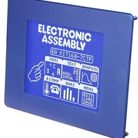
LCD Graphic Display Modules & Accessories Blue/White Contrast RS-232 Snap-In Kit
Manufacturer
ELECTRONIC ASSEMBLY
Datasheet
1.EA_KIT160-7LWTK.pdf
(20 pages)
Specifications of EA KIT160-7LWTK
Pixel Density
160 x 128
Module Size (w X H X T)
129 mm x 102 mm x 33 mm
Viewing Area (w X H)
92.76 mm x 74.2 mm
Backlighting
LED
Background Color
Blue, White
Attached Touch Screen
Yes
Product
Graphic LCD Module
Style
LCD Graphic Display
Interface
RS-232
Display Mode
Blue Negative
Lead Free Status / RoHS Status
Lead free / RoHS Compliant


EA KIT160-7
BAUD RATES
The baud rate can be set by means of the 3 DIP switches on the left. 9,600 baud
is set at the factory (DIP 3 ON). Please note that the internal data buffer only holds
24 bytes. It is therefore imperative that the RTS handshake line be queried (a level
of +10V means data can be accepted; a level of -10V means the display is busy).
The data format is fixed at 8 data bits, 1 stop bit and no parity.
WRITE PROTECTION FOR PROGRAMMED MACROS
You can use DIP switch 6 to prevent the programmed macros,
images and fonts from being inadvertently overwritten.
RS-232/RS-422 CONNECTION
The graphics kit is shipped with an RS-232 interface as standard. The pin assignment of the plug
connector (J3) is as shown in the table on the left. The J3 has a 2.54mm grid. If the graphics kit is ordered
together with the EA OPT-RS4224 optional component, RS-422 drivers are fitted. In this case, the pin
assignment is as shown in the table on the right.
The same serial data with 5V levels and TTL logic is available at the J5 eyelet strip. These levels are
suitable for direct connection to a µC. However, if these signals are used, solder link LB5 and LB6 must
be cut or opened.
SUPPLY VOLTAGE / EA OPT-9/35V
In the standard model, the supply voltage of +5V
is fed in via screw-type terminal J1. In the case of
the version for 9..35V (EA OPT-9/35V), the
power is supplied via J2.
Important: It is imperative that the polarity is
correct. Polarity reversal, even for a very short
time, can cause the immediate destruction of
the entire display.
4
Pin Symbo In/Out
Pin Symbol In/Out
10
1
2
3
4
5
6
7
8
9
1
2
3
4
5
6
7
8
RESET
RS-232 J3 connection
VDD
DCD
DSR
GND
RxD5
RTS5
CTS5
CTS
RTS
DTR
TxD5
RxD
VDD
GND
TxD
VU
-
Out
Out
J5 ad-on
In
In
Out
Out
-
-
-
-
-
-
In
In
In
-
-
-
+ 5V supply
Strap to DTR
Strap to DTR
Transmit data
Clear to send
Receive data
Request to send
See pin 2, pin 3
NC
0V ground
9..35V Supply
+ 5V Supply
0V, Ground
Transmit Data
Receive Data
Request To Send
Clear To Send
H: Reset
Function
Function
DIP
OFF
ON
Write protection
6
No macro progr. possible
Macro progr. possible
Write protection
EEPROM
for
On
Off
Pin
10
1
2
3
4
5
6
7
8
9
RS-422 J3 connection
Data Out+ Transmit data
DIP switches
OFF
OFF OFF
OFF
OFF OFF OFF
Data Out- Transmit data
ON
ON
ON
ON
Symbol
Data In+ Receive data
HS Out+ Handshake
1
HS Out-
Data In-
HS In+
HS In-
VDD
GND
OFF
OFF OFF
ON
ON
ON
ON
2
Baud rates
OFF
OFF
ON
ON
ON
ON
3
+ 5V supply
Receive data
Handshake
Handshake
Handshake
0V ground
Function
Data format
115200
19200
38400
57600
8,N,1
1200
2400
4800
9600
Related parts for EA KIT160-7LWTK
Image
Part Number
Description
Manufacturer
Datasheet
Request
R

Part Number:
Description:
LCD Graphic Display Modules & Accessories Blue/White Contrast RS-232 w/OPT 9/35V
Manufacturer:
ELECTRONIC ASSEMBLY
Datasheet:

Part Number:
Description:
LCD Graphic Display Modules & Accessories Blue/White Contrast RS-232 Snap-In Kit
Manufacturer:
ELECTRONIC ASSEMBLY
Datasheet:
Part Number:
Description:
Display Development Tools StrEval Kit Blk-Wht w/ Intf Exp and CD
Manufacturer:
ELECTRONIC ASSEMBLY
Datasheet:
Part Number:
Description:
Display Development Tools StrEval Kit Blue-Wht w/ Intf Exp and CD
Manufacturer:
ELECTRONIC ASSEMBLY
Datasheet:
Part Number:
Description:
Display Development Tools StrEval Kit Blue-Wht w/ Intf Exp and CD
Manufacturer:
ELECTRONIC ASSEMBLY
Datasheet:
Part Number:
Description:
KIT LPC3141 SODIMM 66X48 200POS
Manufacturer:
Embedded Artists
Datasheet:
Part Number:
Description:
KIT LPC3152 SODIMM 66X48 200POS
Manufacturer:
Embedded Artists
Datasheet:
Part Number:
Description:
KIT LPC3250 259 WITH QVGA
Manufacturer:
Embedded Artists
Datasheet:

Part Number:
Description:
LCD Graphic Display Modules & Accessories Blue/White Contrast RS-232 Snap-In Kit
Manufacturer:
ELECTRONIC ASSEMBLY
Datasheet:

Part Number:
Description:
LCD Touch Panels Touchpanel Analog for DOGM128-6
Manufacturer:
ELECTRONIC ASSEMBLY
Datasheet:
Part Number:
Description:
LCD Touch Panels Touchpanel Analog For DOGS102
Manufacturer:
ELECTRONIC ASSEMBLY
Datasheet:
Part Number:
Description:
LCD Touch Panels Touchpanel Analog For DOGXL160
Manufacturer:
ELECTRONIC ASSEMBLY
Datasheet:
Part Number:
Description:
LCD Touch Panels Touchpanel Analog For DOG-L128-6
Manufacturer:
ELECTRONIC ASSEMBLY
Datasheet:

Part Number:
Description:
LED Displays Bezel 017-xx Series 75.0x24.2/ 91.0x36.4
Manufacturer:
ELECTRONIC ASSEMBLY
Datasheet: