EA STARTEDIP240J ELECTRONIC ASSEMBLY, EA STARTEDIP240J Datasheet - Page 6
EA STARTEDIP240J
Manufacturer Part Number
EA STARTEDIP240J
Description
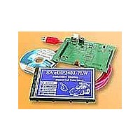
LCD Graphic Display Modules & Accessories Starter/Demoboard w/Touch USB prog
Manufacturer
ELECTRONIC ASSEMBLY
Datasheet
1.EA_EDIP240J-7LATP.pdf
(21 pages)
Specifications of EA STARTEDIP240J
Fluid Type
FSTN Positive
Module Size (w X H X T)
96 mm x 60.4 mm x 10.8 mm
Viewing Area (w X H)
91.18 mm x 56.3 mm
Backlighting
Black / White
Background Color
White
Operating Temperature Range
- 20 C to + 70 C
Attached Touch Screen
Yes
Interface
RS-232, I2C BUS, or SPI BUS
Lead Free Status / RoHS Status
Lead free / RoHS Compliant


EA eDIP240-7
Page 6
SPI INTERFACE
Wiring the display as shown below activates SPI mode. Data is then transferred over the serial,
synchronous SPI interface. The DORD, CPOL and CPHA inputs are used to match the hardware
conditions to the master. For
example (see diagram below).
A reasonable communication is
possible up to 100 kHz.
Clock frequency may be rised up to
3 MHz, but in this case make shure,
that there is a pause between 2
bytes of min. 100 µs.
level to indicate that data is available to be
fetched from the internal send buffer. This
line can, for instance, be connected to an
interrupt input of the host system.
DATA TRANSFER SPI
Via the pins DORD, CPOL and CPHA transfer
parameter will be set.
Write operation: a clock rate up to 100 kHz is allowed
without any stop. Together with a pause of 100 µs
between every data byte a clock rate up to 3 MHz an be
reached.
Read operation: to read data (e.g. the "ACK" byte) a
dummy byte (e.g . 0xFF) need to be sent. Note that the
EA eDIP240-7 for internal operation does need a short
time before providing the data; therefore a short pause of
min. 6µs (no activity of CLK line) is needed for each byte.
Same is with 100kHz operation.
Note:
At pin 20 (SBUF), the display sets a low
Application example
Pin
10
11 SPIMODE
12
13
14
15
16
17 EEP_SDA Bidir. Serial Data Line for int. EEPROM
18 EEP_SCL
19 EEP_WP
20
1
2
3
4
5
6
7
8
9
Symbol
RESET
VOUT
DORD
DPOM
CPOL
CPHA
VADJ
OUT2
BUZZ
SBUF
MOSI
MISO
TEST
GND
VDD
CLK
SS
In/Out Function
Out
Out
Out
Out
Out
Out
IN
In
In
In
In
In
In
In
In
In
In
-
-
-
Ground Potential for logic (0V)
Power supply for logic (+5V)
Operating voltage for LC driving
(input)
Output voltage for LC driving
L: Reset
Slave Select
Serial In
Serial Out
Shift Clock
Data Order (0=MSB first; 1=LSB first)
connect to GND for SPI interface
open-drain with internal pullup 20..50k
(V1.6 or later)
L: disable Power-On-Macro
do not connect for normal operation
Clock Polarity (0=LO 1=HI when idle)
Clock Phase
(sampled on 0=1st 1=2nd edge)
Buzzer output
Serial Clock Line for int. EEPROM
H: Write Protect for int. EEPROM
open-drain with internal pullup 20..50k
IN (Power-On) L: Testmode
OUT L: data in sendbuffer
Pinout eDIP240-7
SPI mode
Pin Symbol Function
21
22
23
24
25
26
27
28
29
30
31
32
33
34
35
36
37
38
39
40
Specifications may be changed without
prior notice. Printing error reserved
N.C.
N.C.
N.C.
N.C.
N.C.
N.C.
N.C.
N.C.
N.C.
N.C.
N.C.
N.C.
N.C.
N.C.
N.C.
N.C.
N.C.
N.C.
N.C.
N.C.
not connected
not connected
not connected
not connected
not connected
not connected
not connected
not connected
not connected
not connected
not connected
not connected
not connected
not connected
not connected
not connected
not connected
not connected
not connected
not connected
Related parts for EA STARTEDIP240J
Image
Part Number
Description
Manufacturer
Datasheet
Request
R

Part Number:
Description:
Display Modules & Development Tools Starter/Demoboard Windows USB For DOGM
Manufacturer:
ELECTRONIC ASSEMBLY

Part Number:
Description:
Display Modules & Development Tools Starter/Demoboard DOGM/ Windows USB
Manufacturer:
ELECTRONIC ASSEMBLY
Datasheet:

Part Number:
Description:
LCD Character Display Modules 4x20 Yellow/Green RS-232 Interface
Manufacturer:
ELECTRONIC ASSEMBLY
Part Number:
Description:
LCD Character Display Modules 4x20 Blue-White RS-232 Interface
Manufacturer:
ELECTRONIC ASSEMBLY
Part Number:
Description:
LCD Character Display Modules 2x16 Yellow/Green RS-232 Interface
Manufacturer:
ELECTRONIC ASSEMBLY

Part Number:
Description:
LCD Character Display Modules STN(+) Reflective Yel/Grn Background
Manufacturer:
ELECTRONIC ASSEMBLY
Datasheet:

Part Number:
Description:
LCD Character Display Modules STN(-) Transmissive Blue Background
Manufacturer:
ELECTRONIC ASSEMBLY
Datasheet:

Part Number:
Description:
LCD Character Display Modules FSTN(-) Transmissive Black Background
Manufacturer:
ELECTRONIC ASSEMBLY
Datasheet:

Part Number:
Description:
LCD Character Display Modules Yel/Green Contrast Yl/Grn LED Backlight
Manufacturer:
ELECTRONIC ASSEMBLY
Datasheet:

Part Number:
Description:
LCD Character Display Modules STN(+) Transmissive Yel/Grn Background
Manufacturer:
ELECTRONIC ASSEMBLY
Datasheet:

Part Number:
Description:
LCD Touch Panels Touchpanel Analog for DOGM128-6
Manufacturer:
ELECTRONIC ASSEMBLY
Datasheet:
Part Number:
Description:
LCD Touch Panels Touchpanel Analog For DOGS102
Manufacturer:
ELECTRONIC ASSEMBLY
Datasheet:
Part Number:
Description:
LCD Touch Panels Touchpanel Analog For DOGXL160
Manufacturer:
ELECTRONIC ASSEMBLY
Datasheet:
Part Number:
Description:
LCD Touch Panels Touchpanel Analog For DOG-L128-6
Manufacturer:
ELECTRONIC ASSEMBLY
Datasheet:

Part Number:
Description:
LED Displays Bezel 017-xx Series 75.0x24.2/ 91.0x36.4
Manufacturer:
ELECTRONIC ASSEMBLY
Datasheet: