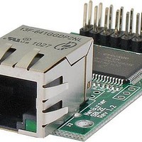
SBL2E-100IR NetBurner Inc, SBL2E-100IR Datasheet - Page 3

SBL2E-100IR
Manufacturer Part Number
SBL2E-100IR
Description
DUAL PORT SERIAL-ETHERNET
Manufacturer
NetBurner Inc
Series
SBL2er
Type
Server, Serial to Ethernetr
Specifications of SBL2E-100IR
Size
2.00" L x 1.20" W (50.8mm x 30.8mm)
Number Of I/os
10
Data Rate
115.2 Kbps
Interface Type
I2C, UART
Operating Voltage
3.3 V
Operating Current
300 mA
Operating Temperature Range
- 40 C to + 85 C
Board Size
1.2 in x 2 in
Data Bus Width
12 bit
Product
Modules
Lead Free Status / RoHS Status
Lead free / RoHS Compliant
Features
-
For Use With/related Products
-
Lead Free Status / Rohs Status
Details
Other names
Q5819275A
SBL2e Pinout and Signal
Description
The SBL2e board has one dual in-line 16 pin header which enables
you to quickly and easily connect to one of our standard NetBurner
Adapter Boards, or a board you create on your own. Table 1 provides
descriptions of pin function of the JP1 Interface Connector.
Table 1: JP1 NetBurner SBL2e Pinout and Signal Descriptions
Table 2: JP3 Board Ethernet Jack Header Pinout and
Signal Descriptions
Table 3: J3 RJ-45 Header Pinout and Signal Descriptions
Note:
1. Asterisk (*) denotes active low. All input/output lines are 3.3V
maximum.
2. All UART signals are TTL Level, external level shifters may be added for
RS-232 or RS-422/485 operation
3. If using I
signals.
4. I
Pin
Pin
Pin
10
10
11
12
10
11
12
13
14
15
16
1
2
3
4
5
6
7
8
9
1
2
3
4
5
6
7
8
9
1
2
3
4
5
6
7
8
9
2
C and UART2 function only available with development kit.
µP Pin
e t B u r n e r
Signal
LDLED
Signal
LDLED
22
21
17
18
68
67
66
65
23
24
79
80
32
SLED
SLED
VCC
VCC
GND
VCC
VCC
VCC
VCC
TX+
RX+
TX+
RX+
TX-
RX-
TX-
RX-
2
NC
NC
NC
Networking in 1 Day!
C, pull-up resistors must be added to open drain SDA/SCL
1
1
1
1
1
1
UART0 CTS
UART0 RTS
UART0 TX
UART0 RX
UART1 RX
UART1 TX
UART2 RX
UART2 TX
Function
ADC0
ADC1
ADC2
ADC3
*RSTI
GND
GND
VCC
Description
Transmit +
Transmit -
Recieve +
No Connect
3.3V
Recieve -
3.3V
Ground
Speed LED
Link LED
Description
Transmit +
Transmit -
Recieve +
3.3V
3.3V
Recieve -
No Connect
No Connect
3.3V
Speed LED
3.3V
Link LED
(1)
*12C SDA
*I2C SCL
Alt. Func.
-
-
-
-
-
-
-
-
-
-
-
-
-
-
3,4
3,4
Note:
1. Optional RJ-45 connector with
integrated magnetics.
2. The 3.3V pins are used for the
magnetics taps and LED power.
Note:
1. Optional 0.1” dual row 10-pin header
2. The 3.3V pins are used for the
magnetics taps and LED power.
GPIO
Yes
Yes
Yes
Yes
Yes
Yes
Yes
Yes
Yes
Yes
-
-
-
-
-
-
Description
UART0 Transmit
UART0 Receive
UART0 Request To Send
UART0 Clear To Send
Input Voltage 3.3VDC
Ground
Analog to Digital Converter 0
Analog to Digital Converter 1
Analog to Digital Converter 2
Analog to Digital Converter 3
Ground
UART1 Receive Data
UART1 Transmit Data
UART2 Receive
UART2 Transmit
Processor Reset Input
1
1,4
1
1,4
(2)
1
1
1
1
(1)
Figure 1: SBL2e-100IR Connector Diagram
Figure 2: SBL2e-200IR Connector Diagram
SBL2e Connector Diagram
The SBL2e board has two dual in-line headers (the v200
board also has the J3 RJ-45 header instead of the jack)
which enables you to quickly and easily connect to one of
our standard NetBurner Adapter Boards, or a board you
create on your own. Tables 1-3 provides descriptions of pin
function of the JP1, JP3 and J3 (v200 only) Interface Con-
nectors and figures 1-2 show their locations.
Integrated
Speed & Link
LEDs
(v100 model)
SBL2e


