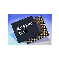
XR17V258IV-F Exar Corporation, XR17V258IV-F Datasheet - Page 37

XR17V258IV-F
Manufacturer Part Number
XR17V258IV-F
Description
IC UART PCI BUS OCTAL 144LQFP
Manufacturer
Exar Corporation
Type
Octal UARTr
Datasheet
1.XR17V258IVTR-F.pdf
(69 pages)
Specifications of XR17V258IV-F
Number Of Channels
8
Package / Case
144-LQFP
Features
*
Fifo's
64 Byte
Protocol
RS485
Voltage - Supply
3.3V, 5V
With Auto Flow Control
Yes
With Irda Encoder/decoder
Yes
With False Start Bit Detection
Yes
With Modem Control
Yes
Mounting Type
Surface Mount
Data Rate
8 Mbps
Supply Voltage (max)
3.6 V
Supply Voltage (min)
3 V
Supply Current
4 mA
Maximum Operating Temperature
+ 85 C
Minimum Operating Temperature
- 45 C
Mounting Style
SMD/SMT
Operating Supply Voltage
3 V to 3.6 V
No. Of Channels
8
Uart Features
Tx/Rx FIFO Counters
Supply Voltage Range
3V To 3.6V
Operating Temperature Range
-40°C To +85°C
Digital Ic Case Style
LQFP
No. Of Pins
144
Rohs Compliant
Yes
Lead Free Status / RoHS Status
Lead free / RoHS Compliant
Lead Free Status / RoHS Status
Lead free / RoHS Compliant, Lead free / RoHS Compliant
Available stocks
Company
Part Number
Manufacturer
Quantity
Price
Company:
Part Number:
XR17V258IV-F
Manufacturer:
EXAR
Quantity:
295
Company:
Part Number:
XR17V258IV-F
Manufacturer:
Exar Corporation
Quantity:
10 000
Part Number:
XR17V258IV-F
Manufacturer:
EXAR/艾科嘉
Quantity:
20 000
REV. 1.0.2
The infrared decoder receives the input pulse from the infrared sensing diode on RX pin. Each time the
decoder senses a light pulse, it returns a "0" to the data bit stream. The RX input signal may be inverted prior
delivered to the input of the decoder via internal register setting. This option supports active LOW instead of
normal active HIGH pulse from some infrared modules on the market.
Each UART channel provides an internal loopback capability for system diagnostic. The internal loopback
mode is enabled by setting MCR register bit [4] to a logic 1. All regular UART functions operate normally.
Figure 14
output is internally routed to the receive shift register input allowing the system to receive the same data that it
was sending. The TX pin is held at HIGH or mark condition while RTS# and DTR# are de-asserted. The CTS#,
DSR#, CD# and RI# inputs are ignored.
4.4
Internal Loopback
shows how the modem port signals are re-configured. Transmit data from the transmit shift register
F
IGURE
Receive
IR Pulse
(RX pin)
RX Data
TX Data
Transmit
IR Pulse
(TX Pin)
13. I
NFRARED
66MHZ PCI BUS OCTAL UART WITH POWER MANAGEMENT SUPPORT
0
Bit Time
Bit Time
0
1
1/16 Clock Delay
T
RANSMIT
1
0
0
1
Character
Data Bits
D
1
ATA
0
37
Data Bits
3/16 Bit Time
Character
0
E
0
NCODING AND
0
1
1 1
1
0
R
0
ECEIVE
1/2 Bit Time
1
1
IRdecoder-
IrEncoder-1
D
ATA
D
ECODING
XR17V258


